XXL Kit for Arduino · Displays
Part 9 The 7-segment display: counting seconds
- Beginner
- Ages 8+
- about 75 min
The section about control is behind us. Now it is time for displays. In this part you will meet the 7-segment display: first a single digit that counts from 0 to 9, and then four digits at once, on which you will build a seconds counter from 0000 to 9999. On the way you will see how seven glowing bars make every digit, and you will learn multiplexing, the trick that lets four digits work on just twelve legs.
Who is it for? For children and teenagers aged 8 and up, for teachers, and for adults who have done Parts 3–8: it helps to know for, if and variables from Part 3. If any of these building blocks is unclear, go back there for a moment.
01
How seven bars make a digit
A 7-segment display is not a screen at all. It is eight LEDs in one case, arranged so that lighting the right ones makes a digit.
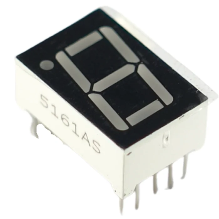
From the kit
1-digit 7-segment display
Eight LEDs in the shape of a digit. Seven bars (the segments) form a figure “8”, and the eighth LED is the decimal point. You light the segments you choose and a digit from 0 to 9 appears on the display, or one of a few letters.
The segments have names from a to g, always in the same order: clockwise, starting from the top bar. g is the bar in the middle:
         a
      ───────
     |       |
   f |       | b
     |   g   |
      ───────
     |       |
   e |       | c
     |   d   |
      ───────   • dp
To show a 3, you light segments a, b, g, c, d and turn off e and f. To show a 1, only b and c are lit. All the rest of this part is about working out which segments to light for which digit, and doing it fast enough.
Every segment is an ordinary LED, the same kind you lit in Part 4, only shaped like a bar. So the same rule applies: every segment needs its own 220 Ω resistor. Without one it will shine beautifully, for the last time.
02
Two types of display and how to check yours
Before you flash the code, you have to know which of the two types you are holding. The wrong type is not a fault: either nothing lights up, or it lights up “inside out”.
All eight LEDs in the display share one common leg, and there are two schools of thought about how to connect it:
| Type | The common leg goes to | A segment lights up when the board pin gives | Note |
|---|---|---|---|
| Common cathode | “–” (GND) | HIGH (5 V) | the most common |
| Common anode | “+” (5 V) | LOW (0 V) | less common |
All the code in this part is written for a common cathode. If you have a common anode, the change in the code is two lines (we will show you which), plus moving the common leg from “–” to “+”.
How to recognize yours: the resistor test. Unplug the USB cable. Take one 220 Ω resistor and use it to connect the “+” rail (5 V) to any leg of the display. This will be your “test segment”. Now take a separate jumper wire and connect the “–” rail (GND) to each of the other legs in turn:
- if at one of them the “test segment” lights up as a single bar, you have a common cathode. The leg you have just connected to “–” is the common cathode, and the one on the resistor is one of the segments.
- if nothing lights up at any leg, swap the sides: run the resistor from the “–” rail to the “test segment”, and use the jumper wire to put “+” on the other legs one by one. Did it light up? You have a common anode.
While you are doing this test, draw on a sheet of paper which leg is which segment (a–g), and for the 4-digit display also which four legs light a whole digit. Manufacturers arrange the pins in different ways. There is usually a code printed on the case (for example 5161AS for one digit, 5641AS for four). Type it into a search engine together with the word “pinout”, and still check with the resistor afterwards, because now and then a display turns up with its legs in a different order.
03
Circuit 1: one digit
Seven resistors and eight wires. It looks crowded, but it is exactly the same connection from Part 4, eight times over.
What you need: the breadboard, the R3 board, the 1-digit 7-segment display, seven 220 Ω resistors, about 9 male-to-male jumper wires.
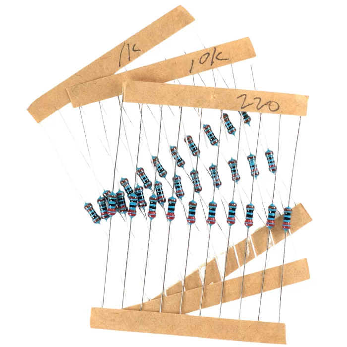
From the kit
Seven 220 Ω resistors
One for every segment. Exactly as with an LED: a resistor goes in series with each bar separately, never one shared resistor on the COM leg. If your kit has fewer 220 Ω resistors than that, 330 Ω or even 1 kΩ will do. The digit will be dimmer, but safe.
The 1-digit display from this kit has 10 legs, 5 on each side, laid out like this:
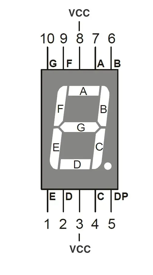
Legs 3 and 8 are one and the same common pin (they are joined inside the case). The picture labels them “VCC”, because it is a typical, general template. That does not mean your display is sure to be a common anode: you check the type anyway, with the resistor test from the section “Two types of display” above. The picture only tells you which leg is which segment.
| Segment | Which bar | Board pin | Note |
|---|---|---|---|
| a | top | D2 | through a 220 Ω resistor |
| b | upper right | D3 | through a 220 Ω resistor |
| c | lower right | D4 | through a 220 Ω resistor |
| d | bottom | D5 | through a 220 Ω resistor |
| e | lower left | D6 | through a 220 Ω resistor |
| f | upper left | D7 | through a 220 Ω resistor |
| g | middle | D8 | through a 220 Ω resistor |
| common (COM) | either of the two – they are joined inside | “–” rail (GND) | common cathode |
| decimal point (DP) | – | – | not used in this part |
  each segment:  pin ──[ 220 Ω ]── segment leg

  D2 ──[ 220 Ω ]── a             a
  D3 ──[ 220 Ω ]── b          ───────
  D4 ──[ 220 Ω ]── c         |       |
  D5 ──[ 220 Ω ]── d       f |   g   | b
  D6 ──[ 220 Ω ]── e          ───────
  D7 ──[ 220 Ω ]── f         |       |
  D8 ──[ 220 Ω ]── g       e |   d   | c
                              ───────   • dp
  COM ──────────── GND
  (common cathode)
This is Circuit 1 built on the breadboard:
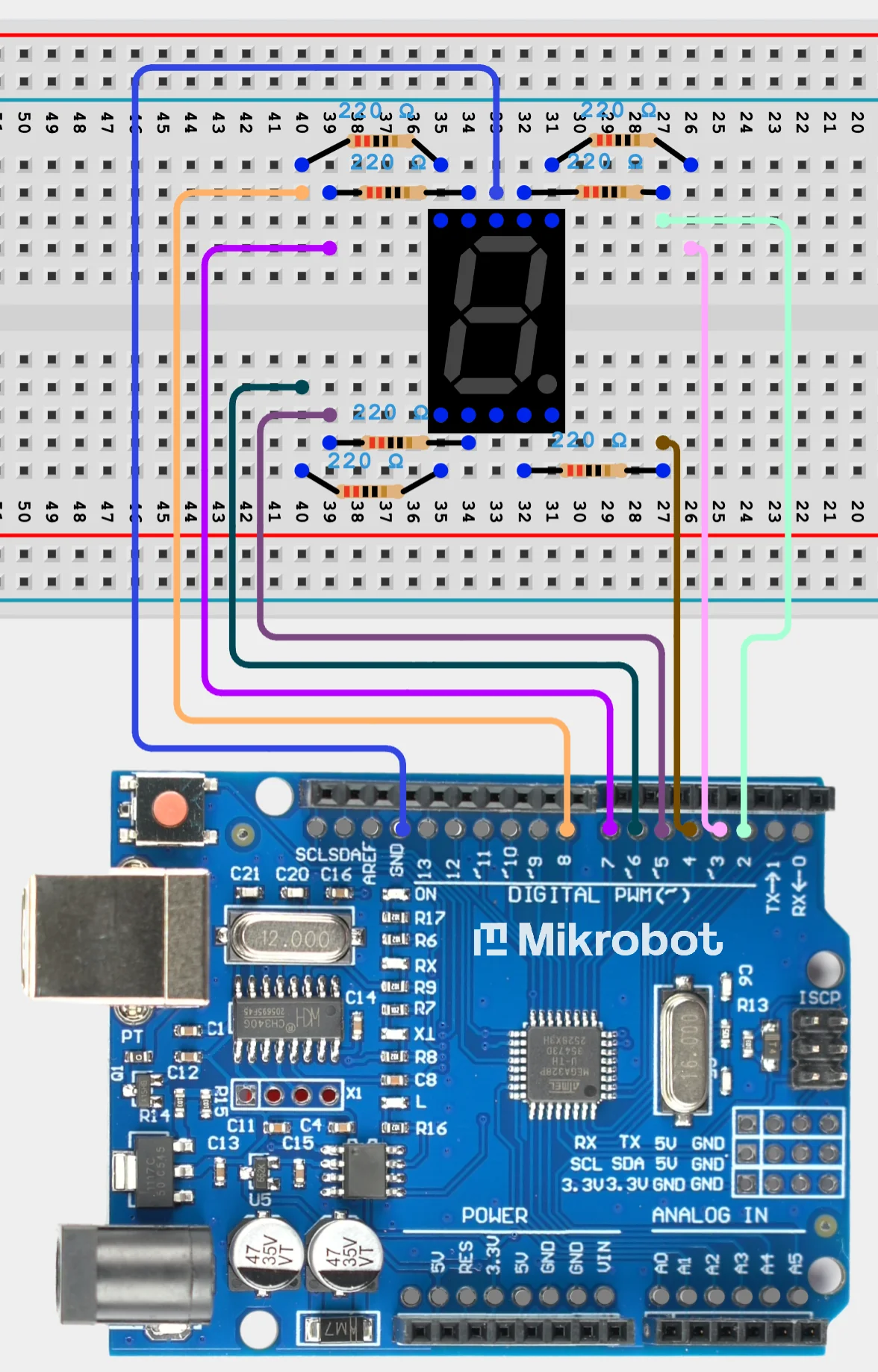
Order of assembly:
- 1Power the rails of the breadboard: one jumper wire from the 5 V pin of the R3 board to the “+” rail, another from the GND pin to the “–” rail. The “+” rail is useful mainly for testing the type of display. With a common cathode the counter itself does not use it.
- 2Push the display into the breadboard straddling the groove: the legs on one side go into one half of the breadboard, the legs on the other side into the other half, the way you plug in a chip.
- 3Plug in the seven 220 Ω resistors: each with one end in a row connected by a jumper wire to one of the pins D2–D8, and the other end in the row with the matching segment leg.
- 4Connect the common leg of the display to the “–” rail (GND) with a jumper wire.
- 5Check the order
a–gagainst your sheet from the resistor test. Mixed-up segments are the most common cause of “gibberish” instead of digits. - 6Check everything once more. Only now plug in the USB cable.
04
Program 1: counting from 0 to 9
The circuit is ready, but dark. First we will tell the board which segments make which digit, in an array.
An array is a table in the code: a series of values under one name, numbered from zero. DIGIT[0] is the first row (the pattern of digit 0), DIGIT[7] is the eighth row (the pattern of digit 7). The second pair of brackets points to the column: DIGIT[7][0] is the first value in the row of digit 7. It says whether segment a should be lit (1) or not (0). Instead of ten ladders of if we have one table that is easy to read.
// === Program 1: a counter 0-9 on one digit ===

const int segmentPins[7] = {2, 3, 4, 5, 6, 7, 8};   // the pins of segments a, b, c, d, e, f, g

// The type of display. By default a common cathode (the common leg goes to "-").
// Do you have a common anode (the common leg goes to "+")? Swap HIGH and LOW below.
const int SEG_ON  = HIGH;   // the pin state that lights a segment
const int SEG_OFF = LOW;    // ... and the one that turns it off

// Which segments are lit for the digits 0-9. In every row in order: a, b, c, d, e, f, g.
const int DIGIT[10][7] = {
  {1, 1, 1, 1, 1, 1, 0},  // 0
  {0, 1, 1, 0, 0, 0, 0},  // 1
  {1, 1, 0, 1, 1, 0, 1},  // 2
  {1, 1, 1, 1, 0, 0, 1},  // 3
  {0, 1, 1, 0, 0, 1, 1},  // 4
  {1, 0, 1, 1, 0, 1, 1},  // 5
  {1, 0, 1, 1, 1, 1, 1},  // 6
  {1, 1, 1, 0, 0, 0, 0},  // 7
  {1, 1, 1, 1, 1, 1, 1},  // 8
  {1, 1, 1, 1, 0, 1, 1},  // 9
};

int number = 0;   // which digit is on the display now

void setup() {
  for (int s = 0; s < 7; s++) {
    pinMode(segmentPins[s], OUTPUT);   // each of the 7 segment pins as an output
  }
}

void loop() {
  // light the segments that match the current digit
  for (int s = 0; s < 7; s++) {
    if (DIGIT[number][s] == 1) {
      digitalWrite(segmentPins[s], SEG_ON);
    } else {
      digitalWrite(segmentPins[s], SEG_OFF);
    }
  }

  delay(1000);              // hold this digit for a second

  number = number + 1;      // go to the next digit
  if (number > 9) {
    number = 0;             // after 9 we go back to 0
  }
}
| Fragment | What it does | Where you know it from |
|---|---|---|
const int segmentPins[7] = { ... } | an array: seven pin numbers under one name | new: an array |
const int DIGIT[10][7] = { ... } | a table of patterns: which segment is lit for which digit | new: an array |
for (int s = 0; s < 7; s++) | go through all seven segments one after another | Part 3 |
if (DIGIT[number][s] == 1) | should segment s be lit for the digit number | Part 3 |
digitalWrite(segmentPins[s], SEG_ON) | light this segment | Part 4 |
delay(1000) | one second for each digit | Part 4 |
number = number + 1 with if (number > 9) | count 0…9 and start over | Part 3 |
Flash the code to the board through FlashESP.com, as in the earlier parts. After flashing, the display runs through 0, 1, 2, … 9 and starts over, one digit every second. If you see random bars instead of digits, the order a–g on pins D2–D8 does not match the array: move the wires or correct your sheet from the test. If the digit shines “in negative” (the background is lit instead of the bars), you have a common anode. Go back to the section about the types.
05
Four digits, twelve legs: multiplexing
Four digits do not mean four times as many wires. It is the same set of seven segments, switched from digit to digit at lightning speed.
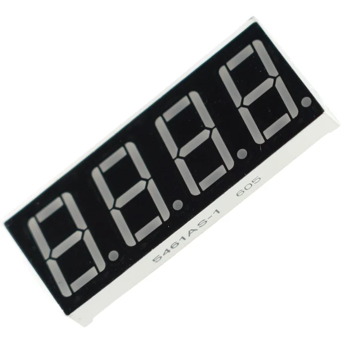
From the kit
4-digit 7-segment display
Four digits, twelve legs. If every digit had eight pins of its own, there would be 32 of them. Instead, all four digits share the same segment legs a–g, and only four “digit select” legs come out separately.
Segment b is one wire shared by all four digits, so you cannot show a 1 on the first digit and a 7 on the second at the same moment. The trick is in the timing:
- 1set the segments to the pattern of the first digit and light only the first digit for about 4 ms,
- 2turn it off, set the segments to the pattern of the second digit, light the second one,
- 3the same for the third and the fourth,
- 4go back to the first, and so on round and round, dozens of times a second.
The eye cannot keep up with such fast switching and sees four digits shining at the same time. For the same reason you see 24 still frames a second as a smooth movie. This technique is called multiplexing: showing things one after another so fast that they seem to be there all at once.
This brings an important change in the code: there must be no delay(1000) in this loop. If there were, the program would freeze for a second on one digit instead of switching between the four. The display has to be refreshed without a break, so we measure the passing of time in a different way: with the instruction millis().
millis() returns the number of milliseconds that have passed since the board was switched on. It does not stop the program. You simply ask “how many so far?” and compare the answer with a value you remembered. When the difference reaches 1000, a second has passed: you add 1 to the counter and remember a new starting point. It is the “remember and compare” trick taken a step further. You used that trick with the button in Parts 5–6 and with the angle of the arm in Part 8.
One more trap: the reversed logic of the digit select legs. With a common cathode a segment is lit by the state HIGH, but a whole digit is “switched on” by the state LOW on its digit select leg. That is because this very leg is the common cathode of the digit and has to carry the current away to ground. In the code we have separate constants for this: SEG_ON and DIGIT_ON.
06
Circuit 2: four digits
The same set of seven resistors on the segments as in Circuit 1. You only add four digit select wires.
What you need: the breadboard, the R3 board, the 4-digit 7-segment display, seven 220 Ω resistors, about 11 male-to-male jumper wires.
The 4-digit display from this kit has 12 legs, 6 on each side, laid out like this:
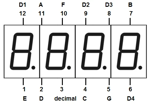
The letters A–G in the picture are the segments (in the text we write them in lower case, a–g), D1–D4 are the digit select legs of the digits counted from the left, and decimal drives the decimal point. This is the most common layout (5641AS). If your display has a different code on its case, check it with the resistor test from the section “Two types of display”.
| Pin | Function | Board pin | Note |
|---|---|---|---|
| segments a–g | shared by all four digits | D2–D8 | each through a 220 Ω resistor (7 of them) |
| digit select 1 | lights the first digit (from the left) | D9 | directly, no resistor |
| digit select 2 | the second digit | D10 | directly |
| digit select 3 | the third digit | D11 | directly |
| digit select 4 | the fourth digit | D12 | directly |
| decimal points (DP), colon | – | – | not used; some displays have a colon for a clock |
  SEGMENTS (shared by all 4 digits, each through 220 Ω):
  D2 ──[ 220 Ω ]── a       D6 ──[ 220 Ω ]── e
  D3 ──[ 220 Ω ]── b       D7 ──[ 220 Ω ]── f
  D4 ──[ 220 Ω ]── c       D8 ──[ 220 Ω ]── g
  D5 ──[ 220 Ω ]── d

  DIGIT SELECT (straight to the pin, no resistor):
  D9  ── digit 1      at any moment only one of these
  D10 ── digit 2      legs is LOW - it belongs to the
  D11 ── digit 3      one digit that is lit right now
  D12 ── digit 4
This is Circuit 2 built on the breadboard:
Step-by-step assembly
Build the circuit on the breadboard
Loading the 3D view...
Connect the “–” rail to GND
With a jumper wire connect the GND pin of the R3 board to the “–” rail. It will come in handy for testing the type of display.
Order of assembly:
- 1Power the “–” rail of the breadboard with a jumper wire from the GND pin of the R3 board (it will also come in handy for testing the type of display).
- 2Push the display into the breadboard straddling the groove, as in Circuit 1.
- 3Plug in the seven 220 Ω resistors between pins D2–D8 and the segment legs
a–g(following your sheet from the test). - 4Connect the four digit select legs directly, with jumper wires, to pins D9, D10, D11, D12. No resistors here.
- 5Check everything once more. Only now plug in the USB cable.
We run the digit select legs straight to the pins, with no resistor. At any moment only one digit is lit, so the current that flows through such a leg is that of a few segments at most. With this small display counting seconds, that works. Bigger multiplexed displays add transistors at this point, so as not to load the pins of the board.
07
Program 2: a seconds counter from 0000 to 9999
The display is ready. This code counts the seconds and keeps refreshing the four digits the whole time, and neither job gets in the way of the other.
The first new thing is your own function. Until now you have only written setup() and loop(). But you can make one of your own: a named piece of code that you call whenever you like, giving it data in the brackets. showDigit(2, 5) means “light the digit 5 in the third position”. Instead of copying the same block out four times, you write it once and call it four times with different numbers.
The second new thing is splitting a number into digits. When it divides whole numbers, the board throws the remainder away: 1234 / 100 is 12, not 12.34. And % (the remainder of a division, you know it from Part 3) picks out the tail end: 1234 % 10 is 4. Put the two together and you can pull out any digit: (1234 / 10) % 10 is 3.
// === Program 2: a seconds counter 0000-9999 on four digits ===

const int segmentPins[7] = {2, 3, 4, 5, 6, 7, 8};   // segments a..g - shared by all the digits
const int digitPins[4]   = {9, 10, 11, 12};         // digit select: 1st, 2nd, 3rd, 4th (from the left)

// The type of display - as in Program 1. Common anode? Swap HIGH and LOW in all four.
const int SEG_ON    = HIGH;   // the segment is lit
const int SEG_OFF   = LOW;
const int DIGIT_ON  = LOW;    // this digit is selected - NOTE: the opposite of a segment
const int DIGIT_OFF = HIGH;   // this digit is off

const int DIGIT[10][7] = {
  {1, 1, 1, 1, 1, 1, 0},  // 0
  {0, 1, 1, 0, 0, 0, 0},  // 1
  {1, 1, 0, 1, 1, 0, 1},  // 2
  {1, 1, 1, 1, 0, 0, 1},  // 3
  {0, 1, 1, 0, 0, 1, 1},  // 4
  {1, 0, 1, 1, 0, 1, 1},  // 5
  {1, 0, 1, 1, 1, 1, 1},  // 6
  {1, 1, 1, 0, 0, 0, 0},  // 7
  {1, 1, 1, 1, 1, 1, 1},  // 8
  {1, 1, 1, 1, 0, 1, 1},  // 9
};

int seconds = 0;                // how many full seconds have passed (0-9999)
unsigned long lastSecond = 0;   // millis() at the moment the last second was added
                                // unsigned long = a roomy box - millis() grows into the billions

void setup() {
  for (int s = 0; s < 7; s++) pinMode(segmentPins[s], OUTPUT);
  for (int d = 0; d < 4; d++) pinMode(digitPins[d], OUTPUT);
}

void loop() {
  // 1. Has another second passed? (no delay - the loop must not stop)
  if (millis() - lastSecond >= 1000) {
    lastSecond = millis();            // remember when it happened
    seconds = seconds + 1;
    if (seconds > 9999) {
      seconds = 0;                    // after 9999 we start over
    }
  }

  // 2. Split the number into four single digits
  int d1 = (seconds / 1000) % 10;   // thousands
  int d2 = (seconds / 100)  % 10;   // hundreds
  int d3 = (seconds / 10)   % 10;   // tens
  int d4 =  seconds         % 10;   // ones

  // 3. Show the digits one after another - each only for a moment (multiplexing)
  showDigit(0, d1);
  showDigit(1, d2);
  showDigit(2, d3);
  showDigit(3, d4);
}

// Your own function: it lights ONE digit.
// position 0-3 (which one from the left), digit 0-9 (what value).
void showDigit(int position, int digit) {
  // a) turn off all four digits - so the previous one does not "leak" through
  for (int d = 0; d < 4; d++) {
    digitalWrite(digitPins[d], DIGIT_OFF);
  }

  // b) set the segments for this digit
  for (int s = 0; s < 7; s++) {
    if (DIGIT[digit][s] == 1) {
      digitalWrite(segmentPins[s], SEG_ON);
    } else {
      digitalWrite(segmentPins[s], SEG_OFF);
    }
  }

  // c) light only the chosen digit
  digitalWrite(digitPins[position], DIGIT_ON);

  delay(4);   // 4 ms per digit -> all 4 digits in ~16 ms, the eye sees a steady picture
}
Write this program in your browser
Tutorial on the left, editor on the right. Build your code and flash it to the board in one click, with nothing to install.
| Instruction | What it does |
|---|---|
millis() | how many milliseconds since the board was switched on – a clock that does not stop the program (Where you know it from: new) |
millis() - lastSecond >= 1000 | another full second has passed (Where you know it from: “remember and compare” from Part 8, taken a step further) |
unsigned long | a roomy box for a number – millis() grows into the billions (Where you know it from: new) |
(seconds / 10) % 10 and similar | picking one digit out of a number (Where you know it from: new – whole-number division and %) |
void showDigit(int position, int digit) | your own function with two parameters (Where you know it from: new – your own function) |
the for loop that turns off all the digits before lighting one | wipes out the “ghost” of the previous digit (Where you know it from: new) |
digitalWrite(digitPins[position], DIGIT_ON) | selects one of the four digits (reversed logic – see above) (Where you know it from: Part 4) |
delay(4) | how long one digit is lit; shorter = less flicker |
Flash the code through FlashESP.com. After flashing, the four digits show 0000 and go up every second: 0001, 0002… all the way to 9999, and then start over. If you see only one digit, a delay(1000) has been left in the loop: count the time with millis() and refresh the digits every few milliseconds. If the “ghost” of the digit next door glimmers beside the right one, then in showDigit() first turn off all the digits, then set the segments, and light one digit last.
Build checklist
Tick them off one by one. Your progress is saved in this browser.
0 / 17
Rules worth remembering
- 1
Every segment is an LED, with its own 220 Ω resistor.
Seven segments without resistors are seven burnt-out LEDs. A resistor goes in series with each line
a–gseparately, never one shared resistor on the COM leg. - 2
First check the type of display, then flash the code.
Common cathode or common anode decides whether a segment is lit by
HIGHor byLOW. The wrong type means a dark display or a digit “in negative”. The resistor test is in the section about the types. - 3
With four digits there is no
delay(1000).A multiplexed display has to be refreshed without a break. You count the seconds with
millis(), without stopping the loop. - 4
You rewire with the USB cable unplugged.
Pull out the cable, fix the wire, check the order
a–gon your sheet, and only then plug it back in.
Projects
None of the projects below needs anything extra: they all build on the same counter. They go from the easiest to the most ambitious.
- 1
A minutes:seconds clock
Easy- What you will use
- Circuit 2
- What you will learn
- splitting the time into
seconds / 60andseconds % 60; using the decimal point between the digits as a separator
- 2
Resetting with a button
Easy- What you will use
- Circuit 2 + a tact switch (Part 5)
- What you will learn
- adding an
INPUT_PULLUPinput next to the display – a press sets the counter to 0
- 3
A stopwatch with a pause
Medium- What you will use
- Circuit 2 + a button
- What you will learn
- stopping and resuming the count – with the time from
millis()remembered at the moment of the pause
- 4
An electronic dice
Medium- What you will use
- Circuit 1 + a button
- What you will learn
- using
random(1, 7)after a press, and making a short “rolling” animation on one digit
- 5
A kitchen timer with an alarm
Challenging- What you will use
- Circuit 2 + the passive buzzer (Part 6)
- What you will learn
- counting down from a set value; at zero
tone()plays the alarm
Summary
A 7-segment display is eight ordinary LEDs dressed up as a digit, with the same iron rule as in Part 4: every segment gets its own 220 Ω resistor. You control one digit directly: an array of patterns says which of the seven bars to light. Four digits need multiplexing: you show them one after another so fast that the eye sees them together. That in turn forces you to use millis() instead of delay(), because the loop must not stop even for a moment.
The array of patterns, your own function and millis() will keep coming back right to the end of the series: with the 8x8 LED matrix in the next part (it is the same idea, only with 64 LEDs instead of 8), with the Snake game and with the clock built on the RTC module.