XXL Kit for Arduino · LED matrix
Part 10 The 8x8 LED matrix: first animations
- Beginner
- Ages 8+
- about 75 min
In Part 9 you multiplexed four digits. Now comes the same trick on a bigger scale: a matrix of 64 LEDs arranged in a square, 8 by 8. You will light a single dot, show a picture drawn in the code with zeros and ones, and finally set it in motion: the first real animation in this series.
Who is it for? For children and teenagers aged 8 and up, for teachers, and for adults who have done Part 9. Multiplexing, the array of patterns and millis() from the previous part come back here almost unchanged. If any of them slipped past you, this is a good moment to go over it again.
01
The 8x8 LED matrix
Sixty-four LEDs on one board. None of them is connected on its own (that would take 128 legs). Instead, they are cleverly joined into a grid.
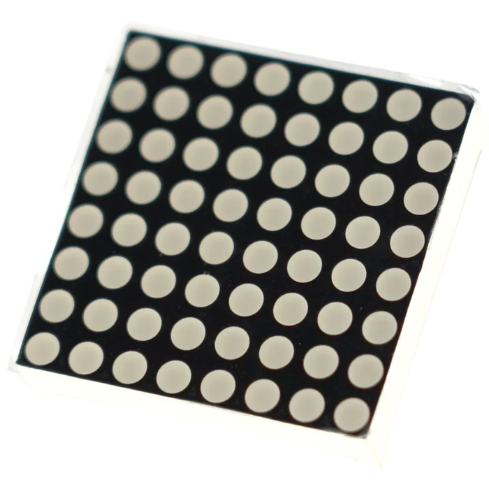
From the kit
8x8 LED matrix
64 LEDs in a square, 8 by 8. Every glowing dot is one LED, just like the green, yellow and red ones from the kit, only here 64 of them are sealed in one case. There are only 16 pins: eight rows and eight columns.
Inside the matrix there are 8 row wires (running across) and 8 column wires (running up and down). Each LED sits where one row crosses one column. Its two legs are kept apart: one is attached to the row wire, the other to the column wire.
         C1 C2 C3 C4 C5 C6 C7 C8      <- columns (8 wires)
  R1  ───┼──┼──┼──┼──┼──┼──┼──┼──
  R2  ───┼──┼──┼──┼──┼──┼──┼──┼──
  R3  ───┼──┼──●──┼──┼──┼──┼──┼──     <- the LED at R3 / C3 is lit
  R4  ───┼──┼──┼──┼──┼──┼──┼──┼──
  R5  ───┼──┼──┼──┼──┼──┼──┼──┼──
  R6  ───┼──┼──┼──┼──┼──┼──┼──┼──
  R7  ───┼──┼──┼──┼──┼──┼──┼──┼──
  R8  ───┼──┼──┼──┼──┼──┼──┼──┼──
   ^
   rows (8 wires)
To light the LED in the 3rd row and the 3rd column, you activate row R3 and column C3. Only the one LED where they cross lights up. The rest of this part is about lighting the right crossings and, just as in Part 9, doing it so fast that the eye sees the whole picture at once.
02
How one LED lights up
A row plus a column. One of them is the “plus” of the LED and the other is the “minus”. Just as with the display from Part 9, there are two schools of thought about which is which.
At all 64 crossings the LEDs face the same way: the anode (plus) to one wire, the cathode (minus) to the other. In the most common type of matrix the anodes are on the row side and the cathodes on the column side.
| Type of matrix | Row | Column | The LED is lit when |
|---|---|---|---|
| row = anode (more common) | anode (+) | cathode (–) | row HIGH, column LOW |
| row = cathode | cathode (–) | anode (+) | row LOW, column HIGH |
The code in this part is written for the first type. If you have the second one, you change four lines (we will show you which) and leave the wires alone.
The resistor test. Unplug the USB cable. Take one 220 Ω resistor and use it to connect the “+” rail (5 V) to any leg of the matrix. Now take a separate jumper wire and connect the “–” rail (GND) to each of the other legs in turn. When exactly one LED lights up, you have found a row–column pair: the leg on “+” through the resistor is the anode side, and the leg on “–” is the cathode side. From the place where the LED lit up, you can also tell which row and which column they really are.
The row legs and the column legs are not neatly separated. There are 8 on each side of the groove, but on most matrices they are mixed up. That is exactly why you should write down all 16 legs on a sheet of paper: which ones are R1–R8 and which are C1–C8. Type the code on the side of the case (for example 1088AS or 1088BS) into a search engine together with the word “pinout”, and you will get a ready drawing. Still check it with the resistor afterwards.
For the matrix from this kit, the legs are laid out like this (looking at the matrix from the front, with the legs at the top and the bottom):
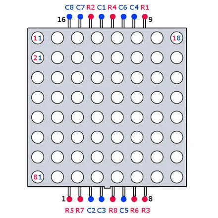
The code 1088BS printed on the side of the case tells you which row of legs is the “bottom” one (legs 1–8 in the picture). Hold the matrix so that this code is underneath, and the legs will match the picture. The labels R1–R8 and C1–C8 are the same ones that the connection table in the next section uses.
03
Multiplexing row by row
You know this from Part 9. There you switched between four digits, and here you switch between eight rows. The rule is exactly the same.
You cannot light any picture you like “in one go”. If you switched on several rows and several columns at once, the LEDs at unwanted crossings would light up too: the so-called ghosts. Say you want to light (R1, C1) and (R2, C2). You switch on rows R1 and R2 and columns C1 and C2, and on the way (R1, C2) and (R2, C1) light up as well, because they also sit on an active crossing.
That is why we draw row by row:
- 1set the 8 columns to the pattern of the first row and light only row R1 for about 2 ms,
- 2turn it off, set the columns to the pattern of row R2, light R2,
- 3and so on through all eight rows,
- 4go back to the first one, a few dozen times a second.
Eight rows of 2 ms each make one full frame about every 16 ms, and the eye sees a still picture. It is exactly the same mechanism as with the four digits in Part 9, only with twice as many rows.
For the animation we add millis() (also from Part 9). The loop keeps refreshing the rows all the time, and every now and then, without stopping it, we swap the picture for a different one. A few pictures one after another make an animation.
04
Building the circuit
Sixteen wires: the most in the whole series. Work in groups of eight and check as you go: first the rows, then the columns.
What you need: a breadboard, the R3 board, the 8x8 LED matrix, eight 220 Ω resistors, about 16 male-to-male jumper wires.
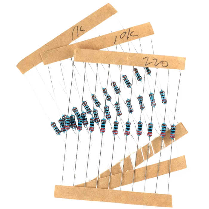
From the kit
Eight 220 Ω resistors
One for every column. The columns are the lines that carry the current of single LEDs, so that is where the resistors go. The rows stay without a resistor, just like the digit select legs in Part 9. If you have fewer 220 Ω resistors, 330 Ω or 1 kΩ ones will do. The picture will be dimmer, but safe.
The legs of the matrix in this kit are mixed up: the rows and the columns do not come in order. The table below is a checked layout. Connect each leg of the matrix to the board pin it shows, and the code will take care of the rest.
| Leg of the matrix | Board pin | 220 Ω resistor |
|---|---|---|
| R1 | D9 | – |
| R2 | D4 | – |
| R3 | D13 | – |
| R4 | D6 | – |
| R5 | A3 | – |
| R6 | D12 | – |
| R7 | A2 | – |
| R8 | D10 | – |
| C1 | D5 | yes |
| C2 | A1 | yes |
| C3 | A0 | yes |
| C4 | D8 | yes |
| C5 | D11 | yes |
| C6 | D7 | yes |
| C7 | D3 | yes |
| C8 | D2 | yes |
  board pin         matrix leg
  D2  ──[ 220 Ω ]──  C8       D10 ─────────────  R8
  D3  ──[ 220 Ω ]──  C7       D11 ──[ 220 Ω ]──  C5
  D4  ─────────────  R2       D12 ─────────────  R6
  D5  ──[ 220 Ω ]──  C1       D13 ─────────────  R3
  D6  ─────────────  R4       A0  ──[ 220 Ω ]──  C3
  D7  ──[ 220 Ω ]──  C6       A1  ──[ 220 Ω ]──  C2
  D8  ──[ 220 Ω ]──  C4       A2  ─────────────  R7
  D9  ─────────────  R1       A3  ─────────────  R5

  [ 220 Ω ] = resistor only on the column lines (C1-C8)
  rows (R1-R8) go straight to a pin
Pins A0–A3 are analog inputs, but they also work perfectly well as ordinary digital outputs: pinMode(A0, OUTPUT) and digitalWrite(A0, HIGH) behave just as they do for D2. There is a built-in L LED on D13, but that does not get in the way of a row line.
How many breadboards. The matrix straddles the groove and leaves just one free hole next to each leg. That is too little to also fit eight resistors there and run 16 wires. To build this whole circuit comfortably on breadboards, you need two of them. If you have only one, don't worry: plug the row legs (R1–R8) straight into the R3 board with female-to-male jumper wires, and use the breadboard only for the eight column lines, the ones that need a resistor.
This is the whole circuit on the wiring diagram:
Step-by-step assembly
Build the circuit on the breadboard
Loading the 3D view...
Plug in the matrix
Push the 8x8 LED matrix into the breadboard straddling the groove, with 8 legs on each side and the 1088BS code on its side facing away from you. One free hole is left next to each leg: in row A and in row J.
Order of assembly:
- 1Push the matrix into the breadboard straddling the groove, with 8 legs on each side.
- 2Connect the 8 row legs (R1–R8) with jumper wires straight to the pins from the table: D9, D4, D13, D6, A3, D12, A2, D10.
- 3Plug in the eight 220 Ω resistors, each one between a column pin (D5, A1, A0, D8, D11, D7, D3, D2) and a column leg C1–C8.
- 4Check once more that the rows and the columns have not got mixed up: with 16 legs that is the most common mistake. If your matrix has a different layout of legs than the table, write down your own with the resistor test from the section “How one LED lights up”, and also correct the arrays
rowPins/columnPinsin the code. - 5Check everything once more. Only now plug in the USB cable.
We run the rows straight to the pins. When many columns in one row are lit at once, that row's pin carries the current of up to eight LEDs: more than a board pin likes to give all the time. With the sparse patterns of this part and a short flash (each row is lit only ⅛ of the time) it works. A bright, densely lit screen needs a driver chip, for example the MAX7219 (it is not in this kit), or transistors on the rows.
Before you flash the real program: a quick test of the connections. With sixteen wires it can happen that one jumper wire does not make good contact, and hunting for a fault like that in a finished game or animation is tiring. First flash this short test sketch. It lights the whole matrix at once, row by row:
// Test: lights the whole matrix - checks the connections before the real program
const int rowPins[8]    = {9, 4, 13, 6, A3, 12, A2, 10};
const int columnPins[8] = {5, A1, A0, 8, 11, 7, 3, 2};

const int ROW_ON  = HIGH;
const int ROW_OFF = LOW;
const int COL_ON  = LOW;
const int COL_OFF = HIGH;

void setup() {
  for (int i = 0; i < 8; i++) {
    pinMode(rowPins[i], OUTPUT);
    pinMode(columnPins[i], OUTPUT);
  }
}

void loop() {
  for (int r = 0; r < 8; r++) {
    for (int i = 0; i < 8; i++) digitalWrite(rowPins[i], ROW_OFF);    // turn off all the rows
    for (int c = 0; c < 8; c++) digitalWrite(columnPins[c], COL_ON);  // all the columns on
    digitalWrite(rowPins[r], ROW_ON);                                 // light this one row
    delay(2);
  }
}
It is the same multiplexing as in the programs below, row by row, 2 ms each, only instead of the pattern from the IMAGE array, all eight columns light up at once in every row. All 64 LEDs should shine equally brightly, with no dark rows, columns or single dots.
If something is missing, don't look for a mistake in the code of a game or an animation yet. Wiggle each jumper wire at the matrix and at the resistors, one after another: a loose contact is the most common cause of dark or flickering patches. Only when the whole matrix shines evenly, move on to the real program below.
05
Program 1: a dot and a picture
First a single LED in the middle. Then you swap eight lines of the array and get a smiley face.
We keep the picture in an 8x8 array, like DIGIT in Part 9, only bigger. 1 means “the LED is lit”, 0 means “dark”. You read the array like a drawing: you look at the zeros and ones and see the shape.
// === Program 1: a picture on the 8x8 matrix ===

// Order = R1..R8 and C1..C8 (from the connection table for this kit).
const int rowPins[8]    = {9, 4, 13, 6, A3, 12, A2, 10};   // rows R1..R8
const int columnPins[8] = {5, A1, A0, 8, 11, 7, 3, 2};     // columns C1..C8

// Type of matrix. Default: row = anode (+), column = cathode (-), e.g. 1088AS.
// A different type? Swap HIGH and LOW in these four lines.
const int ROW_ON  = HIGH;    // this row is being scanned now
const int ROW_OFF = LOW;
const int COL_ON  = LOW;     // the LED in this column is lit - NOTE: the opposite of the row
const int COL_OFF = HIGH;

// The picture: 1 = LED lit, 0 = dark. Eight rows of eight values.
// Here: one dot in the middle (4th row, 4th column).
const int IMAGE[8][8] = {
  {0, 0, 0, 0, 0, 0, 0, 0},
  {0, 0, 0, 0, 0, 0, 0, 0},
  {0, 0, 0, 0, 0, 0, 0, 0},
  {0, 0, 0, 1, 0, 0, 0, 0},
  {0, 0, 0, 0, 0, 0, 0, 0},
  {0, 0, 0, 0, 0, 0, 0, 0},
  {0, 0, 0, 0, 0, 0, 0, 0},
  {0, 0, 0, 0, 0, 0, 0, 0},
};

void setup() {
  for (int i = 0; i < 8; i++) {
    pinMode(rowPins[i], OUTPUT);
    pinMode(columnPins[i], OUTPUT);
  }
}

void loop() {
  for (int r = 0; r < 8; r++) {
    showRow(r);
  }
}

// Lights one row of the picture (r = 0..7).
void showRow(int r) {
  // a) turn off all the rows - so that no "ghosts" are left from the previous one
  for (int i = 0; i < 8; i++) {
    digitalWrite(rowPins[i], ROW_OFF);
  }

  // b) set the 8 columns to the pattern in this row
  for (int c = 0; c < 8; c++) {
    if (IMAGE[r][c] == 1) {
      digitalWrite(columnPins[c], COL_ON);
    } else {
      digitalWrite(columnPins[c], COL_OFF);
    }
  }

  // c) light only this row
  digitalWrite(rowPins[r], ROW_ON);

  delay(2);   // 2 ms per row -> a full frame of 8 rows in ~16 ms
}
How to read showRow(). The matrix has eight rows, but we can light only one at a time. It is as if you had one flashlight and shone it on the lines of a book, one after another. The function showRow(r) “lights up” one line, row number r, in three steps:
- 1It turns off all eight rows. Before we change the columns, the whole matrix has to be dark. Otherwise, for a split second, the LEDs of the previous row would light up in the new places: those are the “ghosts”.
- 2It sets the eight columns according to the drawing. The program looks at row
rof theIMAGEarray and, for each of the eight columns, says “light up here” (COL_ON) or “dark here” (COL_OFF). Nothing lights up yet, because all the rows are still off. This is just getting ready. - 3It lights row
r. Only now. The only LEDs that shine are the ones where a lit row meets a lit column, which means exactly the dots in rowrof the drawing. It is like a seat in a cinema: both the row number and the seat number have to match.
At the end, delay(2) keeps this one row lit for 2 milliseconds, and the function ends. loop() calls showRow(0), showRow(1), … showRow(7) over and over without end. Eight rows of 2 ms each make one full picture about every 16 ms, which is more than 60 times a second. The eye cannot keep up with this blinking and sees a still picture: for now, one dot in the middle.
To turn the dot into a smiley face, replace the eight lines of IMAGE with a drawing of a face. The rest of the program stays the same:
const int IMAGE[8][8] = {
  {0, 0, 1, 1, 1, 1, 0, 0},
  {0, 1, 0, 0, 0, 0, 1, 0},
  {1, 0, 1, 0, 0, 1, 0, 1},
  {1, 0, 0, 0, 0, 0, 0, 1},
  {1, 0, 1, 0, 0, 1, 0, 1},
  {1, 0, 0, 1, 1, 0, 0, 1},
  {0, 1, 0, 0, 0, 0, 1, 0},
  {0, 0, 1, 1, 1, 1, 0, 0},
};
| Fragment | What it does | Where you know it from |
|---|---|---|
const int rowPins[8] / columnPins[8] | pin numbers in the order R1…R8 and C1…C8 (from the connection table) | an array, Part 9 |
A0, A1, A2, A3 in the pin arrays | analog inputs used as ordinary outputs | new: an analog pin as OUTPUT |
const int IMAGE[8][8] | the drawing: 1 lit, 0 dark | a bigger array, Part 9 |
void showRow(int r) | lights one row of the picture | your own function, Part 9 |
the for that turns off all the rows before lighting one | wipes out the “ghosts” | Part 9 |
delay(2) | how long one row is lit; 8 × 2 ms = a frame of ~16 ms | Part 9 |
Flash the code through FlashESP.com. After flashing, one dot shines in the middle of the matrix. When you swap IMAGE for the smiley face and flash again, you get a face. If a whole row or a whole column lights up instead of the pattern, the rows and the columns are mixed up: check your sheet from the test. If the picture is “in negative” (the background is lit and the shape is missing), you have the other type of matrix: swap HIGH and LOW in the constants ROW_* and COL_*. If the picture is rotated or mirrored, the rows or the columns are in a different order: move the wires, or change the order in rowPins / columnPins.
06
Program 2: animation
An animation is nothing more than showing different pictures one after another. Here there are two: a smiley face with its eyes open, and a smiley face that has just winked.
We keep two frames: FRAME_A (eyes open) and FRAME_B (right eye closed). millis() decides which of them we draw: we hold frame A for a long time and frame B only for a moment. The loop keeps multiplexing the current frame all the time, exactly as in Program 1.
// === Program 2: a winking smiley face on the 8x8 matrix ===

// Order = R1..R8 and C1..C8 (from the connection table for this kit).
const int rowPins[8]    = {9, 4, 13, 6, A3, 12, A2, 10};
const int columnPins[8] = {5, A1, A0, 8, 11, 7, 3, 2};

const int ROW_ON  = HIGH;    // a different type of matrix? swap HIGH and LOW in these four
const int ROW_OFF = LOW;
const int COL_ON  = LOW;
const int COL_OFF = HIGH;

// Frame A: eyes open
const int FRAME_A[8][8] = {
  {0, 0, 1, 1, 1, 1, 0, 0},
  {0, 1, 0, 0, 0, 0, 1, 0},
  {1, 0, 1, 0, 0, 1, 0, 1},
  {1, 0, 0, 0, 0, 0, 0, 1},
  {1, 0, 1, 0, 0, 1, 0, 1},
  {1, 0, 0, 1, 1, 0, 0, 1},
  {0, 1, 0, 0, 0, 0, 1, 0},
  {0, 0, 1, 1, 1, 1, 0, 0},
};

// Frame B: right eye closed (a wink)
const int FRAME_B[8][8] = {
  {0, 0, 1, 1, 1, 1, 0, 0},
  {0, 1, 0, 0, 0, 0, 1, 0},
  {1, 0, 1, 0, 0, 0, 0, 1},
  {1, 0, 0, 0, 0, 1, 0, 1},
  {1, 0, 1, 0, 0, 0, 0, 1},
  {1, 0, 0, 1, 1, 0, 0, 1},
  {0, 1, 0, 0, 0, 0, 1, 0},
  {0, 0, 1, 1, 1, 1, 0, 0},
};

int frame = 0;                 // 0 = FRAME_A, 1 = FRAME_B
unsigned long lastChange = 0;  // millis() of the last change of frame

void setup() {
  for (int i = 0; i < 8; i++) {
    pinMode(rowPins[i], OUTPUT);
    pinMode(columnPins[i], OUTPUT);
  }
}

void loop() {
  // 1. Change of frame: hold A for 2000 ms, B only for 150 ms (a short wink)
  int holdTime;
  if (frame == 0) {
    holdTime = 2000;
  } else {
    holdTime = 150;
  }

  if (millis() - lastChange >= holdTime) {
    lastChange = millis();
    frame = frame + 1;
    if (frame > 1) {
      frame = 0;
    }
  }

  // 2. Draw the current frame, row by row
  for (int r = 0; r < 8; r++) {
    showRow(r);
  }
}

void showRow(int r) {
  for (int i = 0; i < 8; i++) {
    digitalWrite(rowPins[i], ROW_OFF);
  }

  for (int c = 0; c < 8; c++) {
    int lit;
    if (frame == 0) {
      lit = FRAME_A[r][c];
    } else {
      lit = FRAME_B[r][c];
    }

    if (lit == 1) {
      digitalWrite(columnPins[c], COL_ON);
    } else {
      digitalWrite(columnPins[c], COL_OFF);
    }
  }

  digitalWrite(rowPins[r], ROW_ON);
  delay(2);
}
Write this program in your browser
Tutorial on the left, editor on the right. Build your code and flash it to the board in one click, with nothing to install.
| Instruction | What it does |
|---|---|
FRAME_A, FRAME_B | the two pictures of the animation (Where you know it from: an array, Part 9) |
frame with if (frame > 1) frame = 0 | which frame is on the screen now (Where you know it from: a counter as in Part 9) |
if (frame == 0) holdTime = 2000 | the eyes stay open longer, the wink is short (Where you know it from: if, Part 3) |
millis() - lastChange >= holdTime | time to change the frame, without stopping the loop (Where you know it from: millis(), Part 9) |
lit = FRAME_A[r][c] or FRAME_B[r][c] | which frame to take the row's pattern from (Where you know it from: if, Part 3) |
After flashing, the smiley face looks at you and every now and then winks its right eye. Change 2000 and 150 to make it wink less often or more often. Add FRAME_C, extend the condition to if (frame > 2) and take the pattern from it in showRow(): you get a longer animation.
Build checklist
Tick them off one by one. Your progress is saved in this browser.
0 / 16
Rules worth remembering
- 1
Resistors on the columns, not on the rows.
A column carries the current of one LED, a row carries the current of up to eight. The eight 220 Ω resistors go on the eight column lines.
- 2
Check the type of matrix before you flash the code.
Whether the row is the anode or the cathode decides if the LED is lit by
HIGHor byLOWon the row. The wrong type means a picture in negative or a dark matrix. - 3
Animation means
millis(), notdelay().The matrix has to be multiplexed without a break. You switch the frames while counting the time in the background, just as in Part 9.
- 4
With 16 wires, a plan on paper is not a luxury.
Draw which leg is which row and which column. Always move the wires with the USB cable unplugged.
Projects
None of the projects below needs anything extra: they all build on the same circuit. They go from the easiest to the most ambitious.
- 1
A wandering dot
Easy- What you will use
- this circuit
- What you will learn
- moving one lit LED step by step with
millis(), using the variablesxandyinstead of a whole array
- 2
A bouncing dot
Easy- What you will use
- this circuit
- What you will learn
- giving a dot a direction of +1 / −1 on each axis so that it turns back at the edges, like the automatic mode from Part 8
- 3
Falling drops
Medium- What you will use
- this circuit
- What you will learn
- handling several dots, each with its own position and speed: an array of positions instead of a picture
- 4
Drawing with the joystick
Medium- What you will use
- this circuit + the joystick (Part 11)
- What you will learn
- moving a dot around the matrix with the two axes of the joystick, while the button “leaves a trail”
- 5
Scrolling text
Challenging- What you will use
- this circuit
- What you will learn
- keeping an array of letter patterns and shifting the picture by one column at a time with
millis(): “scrolling text” like the one above a shop
Summary
The 8x8 matrix brought in almost no new rule. It is Part 9 spread over eight rows instead of four digits: the same scan row by row, the same array of patterns (only 8 by 8), the same millis() to switch the frames. Really only one thing was new: you draw the picture in the code with zeros and ones, and you see right away what will light up.
That rounds off the basics of displays. From the next part on, we combine them with inputs: the joystick will steer a servo, and then a dot on this very matrix, all the way to the game Snake.