XXL Kit for Arduino · Joystick
Part 11 Controlling a servo with a joystick
- Beginner
- Ages 8+
- about 45 min
In Part 7 you controlled a servo by turning the knob of a potentiometer. Now you will swap the knob for a joystick: the same idea, a better input. The code that controls the servo stays almost the same as in Part 7. What changes is where the number comes from, and two things arrive that the knob did not have: a center that springs back and a dead zone around it.
Who is it for? For children and teenagers aged 8 and up, for teachers, and for adults who have done Part 7. If you have not done Part 7, start with it: here we only build on that circuit.
01
What a joystick really is
Three parts you already know, squeezed into one case with a stick.
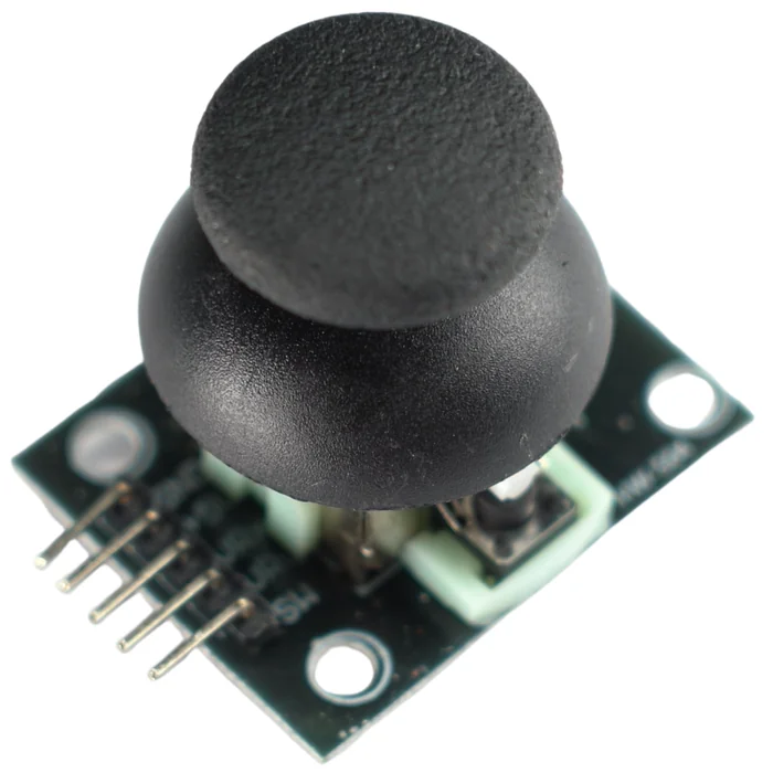
From the kit
Joystick module
Two axes plus a button. Inside it has two potentiometers set at right angles, one measuring the tilt left and right (the X axis) and the other forward and back (the Y axis), and a button under the stick, which closes when you push the stick down.
In other words: a joystick is the potentiometer from Parts 5 and 7 taken twice, plus the tact switch from Part 5. Nothing new as far as the electronics go. The only new thing is the way you hold it in your hand.
02
Connecting the module
A ready-made module has its own pin header, so this time the breadboard is not needed.
The joystick has five pins brought out to a header. You connect them to the R3 board with female-to-male jumper wires (the socket goes onto the module's pin, the plug into the R3 board).
| Joystick pin | Goes to | Note |
|---|---|---|
| GND | GND of the R3 board | ground |
| +5V (sometimes “5V” or “VCC”) | 5 V of the R3 board | power |
| VRx | A0 | the X axis as a number 0–1023 |
| VRy | A1 | the Y axis – in this part we only watch it |
| SW | D2 | pressing the stick; in the code INPUT_PULLUP |
You connect the servo exactly as in Part 7:
| Servo | Goes to |
|---|---|
| brown/black wire | GND |
| red wire | 5 V |
| orange/yellow wire | pin 9 |
  JOYSTICK (module, 5 pins -> female-to-male jumper wires):
  GND  --- GND
  +5V  --- 5V
  VRx  --- A0     (X axis: 0..1023, center ~512)
  VRy  --- A1     (Y axis: for now only watched in the monitor)
  SW   --- D2     (pressing the stick, INPUT_PULLUP)

  SERVO (as in Part 7):
  brown --- GND      red --- 5V      orange --- pin 9
This is the whole circuit on the wiring diagram:
Step-by-step assembly
Build the circuit on the breadboard
Loading the 3D view...
Connect the joystick
Plug five female-to-male jumper wires into the joystick's header and the other ends straight into the R3 board: GND to GND, +5V to 5V, VRx to A0, VRy to A1, SW to pin 2.
Order of assembly:
- 1Plug five female-to-male jumper wires into the joystick's header: GND, +5V, VRx, VRy, SW.
- 2The other ends: GND → GND, +5V → 5 V, VRx → A0, VRy → A1, SW → D2.
- 3Connect the servo: brown → GND, red → 5 V, orange → pin 9.
- 4Check everything. Only now plug in the USB cable.
- 5Attach a cardboard arm to the servo's horn so that you can see the movement.
03
See what the joystick prints
Before you connect it to the servo, look at the bare numbers. It is the best way to understand the stick.
const int xPin      = A0;  // the joystick's X axis
const int yPin      = A1;  // the joystick's Y axis
const int buttonPin = 2;   // pressing the stick (SW)

void setup() {
  Serial.begin(9600);
  pinMode(buttonPin, INPUT_PULLUP);  // SW connects to ground when pressed - it needs a pull-up
}

void loop() {
  Serial.print("X: ");
  Serial.print(analogRead(xPin));         // center ~512, ends ~0 and ~1023
  Serial.print("   Y: ");
  Serial.print(analogRead(yPin));
  Serial.print("   button: ");
  Serial.println(digitalRead(buttonPin)); // 1 = released, 0 = pressed
  delay(200);
}
Flash this program through FlashESP.com and open the Serial Monitor (we showed it in Part 3). Move the stick: X and Y jump between ~0 and ~1023, and when you let go they come back close to 512, because the stick has a spring and centers itself. Push the stick down: button changes from 1 to 0.
Write down the values that your joystick shows at rest. For one it will be 505, for another 520. That is normal, and in a moment it will matter.
04
The same as in Part 7
The heart of the circuit does not change. The joystick goes in exactly where the potentiometer was in Part 7.
- The same actuator: the SG90 servo, the same
Servolibrary, the same commandsservo.attach(9)andservo.write(angle). - The same skeleton of the loop: read the analog input → convert with
map(reading, 0, 1023, 0, 180)→ send the angle to the servo. - One axis of the joystick = one potentiometer.
analogRead(A0)returns a number 0–1023, just like the knob in Part 7. The stick pushed all the way gives ~0 and ~1023, the center is ~512. - The same warning about power: power a servo under load separately (4.8–6 V, common ground). The details are in Part 7.
- The same fix for the direction: if the servo goes the opposite way to the stick, swap
0and180inmap(), as in Parts 5 and 7.
05
What is new compared with Part 7
The knob stayed where you let go of it. The stick always returns to the center, and that changes how you think about the input.
1. The center is now a definite number. A potentiometer at rest has any value: the one you left it on. A joystick at rest has ~512, which means ~90°. The resting state of the input is no longer a matter of chance, and the code can rely on it.
2. A dead zone around the center. The joystick does not return to exactly 512 (sometimes 505, sometimes 520), and it wobbles as well. If we did nothing about it, the servo would “creep” by itself in tiny movements when nobody is touching the stick. So we add a few lines: we treat every value close to the center as equal to 512. You know the idea from Part 8, where there was a dead zone for the direction LEDs.
3. Two axes instead of one. The joystick gives VRx and VRy: two independent readings (A0 and A1). Here we use one for the servo, and for now we only watch the other in the Serial Monitor. In the projects you will connect it to something more.
4. The button comes included. Pushing the stick down is a built-in button (the SW pin). You do not add a separate tact switch. You read it the same way, through INPUT_PULLUP, and here we will use it to center the servo with one press.
5. A ready-made module, not a bare part. In Part 7 you plugged the potentiometer's three legs into the breadboard and made a voltage divider out of it yourself. The joystick has its dividers inside: you connect five female-to-male jumper wires straight to the header, and no breadboard is needed.
| Part 7 (potentiometer) | Part 11 (joystick) | |
|---|---|---|
| Input | a bare potentiometer in the breadboard | a ready-made module, 5 pins, female-to-male jumper wires |
| At rest | wherever you leave the knob | a spring, it returns to the center by itself (~512) |
| Number of axes | one | two (X and Y) |
| Button | a separate tact switch or none | built into the stick |
| Code that controls the servo | analogRead → map → servo.write | the same plus a dead zone around the center |
06
The program: the servo follows the stick
Take the code from Part 7, connect the input to the joystick's X axis and add two things: a dead zone and the button.
#include <Servo.h>            // the servo library - you met it in Part 7

const int xPin      = A0;     // the joystick's X axis - it is a potentiometer inside the module
const int buttonPin = 2;      // pressing the stick (SW)

Servo servo;                  // a "remote control" for the servo - as in Part 7

void setup() {
  servo.attach(9);                      // the servo's signal wire on pin 9
  pinMode(buttonPin, INPUT_PULLUP);     // the joystick's built-in button
}

void loop() {
  int reading = analogRead(xPin);       // 0 - 1023, center ~512

  if (reading > 480 && reading < 544) { // a value close to the center...
    reading = 512;                      // ...treat it as the exact center (dead zone)
  }

  int angle = map(reading, 0, 1023, 0, 180); // convert to an angle - exactly as in Part 7
  servo.write(angle);                   // send the angle to the servo

  if (digitalRead(buttonPin) == LOW) {  // the stick is pressed...
    servo.write(90);                    // ...set the servo to the center
  }

  delay(20);                            // a steady pace for the loop
}
Write this program in your browser
Tutorial on the left, editor on the right. Build your code and flash it to the board in one click, with nothing to install.
| Instruction | What it does |
|---|---|
#include <Servo.h> + servo.attach(9) | connects the servo (Where you know it from: Part 7) |
analogRead(xPin) + map(..., 0, 180) | the joystick's X axis → the servo's angle (Where you know it from: Part 7 (there a knob instead of an axis)) |
if (reading > 480 && reading < 544) reading = 512; | the dead zone – it stops the servo from “creeping” at rest (Where you know it from: the dead zone from Part 8, taken further) |
pinMode(buttonPin, INPUT_PULLUP) + digitalRead | reads the stick's built-in button (Where you know it from: Part 5) |
servo.write(90) when pressed | one press centers the servo (Where you know it from: new in this part) |
This program uses the library Servo 1.3.0. It is already added to the project in the editor next to the lesson.
Flash the code through FlashESP.com. Tilt the stick left and right: the servo's arm follows it. Let go of the stick: the servo returns to the center and stands still (that is thanks to the dead zone). Push the stick down: the servo jumps to 90° and holds it for as long as you hold the stick. If something is not right, go through the checklist below.
Build checklist
Tick them off one by one. Your progress is saved in this browser.
0 / 12
Rules worth remembering
- 1
The center of a joystick is not zero.
A released stick gives ~512, not 0. The code has to assume that, or the servo will “run off” to the end as soon as you let go of the stick.
- 2
A dead zone around the center is a must.
The joystick returns to the center unevenly and wobbles. Without a few lines that say “close to the center = the center”, the servo creeps by itself.
- 3
A servo under load gets its own power.
The same rule as in Part 7: if the servo trembles or the board resets, give the servo its own 4.8–6 V and a common ground.
- 4
A joystick means five female-to-male jumper wires.
The module has its own pin header. You do not plug it into the breadboard.
Projects
None of the projects below needs anything extra: they build on the same circuit. They go from the easiest to the most ambitious.
- 1
Calibrating the stick
Easy- What you will use
- the joystick + the Serial Monitor
- What you will learn
- printing X and Y to find the resting values of your own joystick, and setting the dead zone to fit them
- 2
Controlling speed, not position
Easy- What you will use
- the joystick + the servo
- What you will learn
- making the servo turn faster the further the stick is from the center –
anglechanges by a step that depends on the tilt
- 3
Center and hold
Medium- What you will use
- the joystick + the servo
- What you will learn
- using the button to switch between “the servo listens to the stick” and “the servo stays at 90°” – a latch (toggle), as in Parts 5–6
- 4
A second axis = a second LED
Medium- What you will use
- the joystick + two LEDs + two 220 Ω resistors
- What you will learn
- lighting one of the LEDs depending on which way the Y axis is tilted – a second
analogReadand thresholds
- 5
Record and replay a movement
Challenging- What you will use
- the joystick + the servo
- What you will learn
- guiding the servo with the stick while you hold the button, as the program saves each angle in an array; when you let go, it replays the movement in a loop
Summary
The joystick is not a new chapter. It is Part 7 with a better input. The code that controls the servo stayed almost the same: analogRead → map → servo.write. What is new is knowing that an input can have a center it returns to by itself, and that it then needs a dead zone so that small wobbles do not move the servo. Along the way you saw that a ready-made module can pack in several parts that you used to plug in separately.
In the next part the same stick will control something that is no longer physical: a snake on the LED matrix.