XXL Kit for Arduino · Project
Part 8 A control panel for a robot arm
- Beginner
- Ages 8+
- about 60 min
This is the last part about control, and the first in which all the parts you have met work together in one device. You will build a robot arm control panel: you set the angle with a knob, you switch between manual mode and an automatic cycle with a button, three LEDs show the direction of movement, and a buzzer sounds the alarm when the arm reaches the end of its range. There is not much new code. Most of it is things you already know, just put together.
Who is it for? For children and teenagers aged 8 and up, for teachers, and for adults who have done Parts 5–7. This is a good place for a review: if any piece is unclear, go back to the part it comes from. We point to it each time.
01
What exactly we are building
A model of something that really stands in a factory.
Real manipulators on assembly lines (the ones that weld car bodies, stack boxes on pallets or carry parts from one station to the next) and overhead cranes in warehouses have exactly the same four things on the operator's panel:
- a knob or a joystick for setting the position by hand,
- a mode switch: manual (the operator guides the machine) or automatic (the machine repeats a programmed cycle),
- direction lights: lamps or flashing beacons that show which way the machine is moving, so that nobody walks into its path,
- a limit switch signal: a buzzer or a siren that warns that the moving part has reached the end of its range.
The SG90 servo will play the role of the rotating base of the arm: it turns horizontally, left and right. Attach the little propeller of your choice to the servo. That is your “arm”. The rest of the parts are the panel you control it from.
02
The parts and where you know them from
Not a single new component. Each one has appeared before. Here is just a reminder of what it is for and which part explained it.
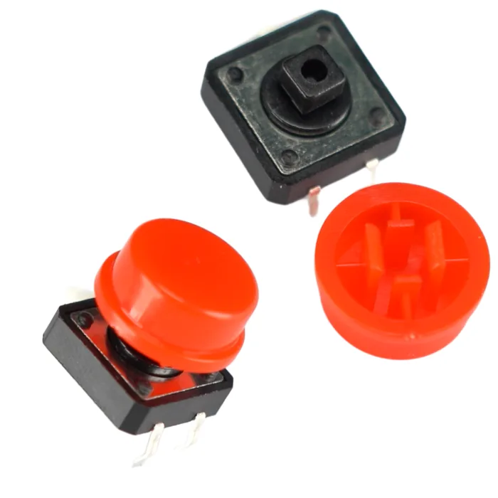
From the kit
Tact switch button – the manual / automatic mode switch
A digital input with INPUT_PULLUP and detecting a press – Parts 5 and 6.
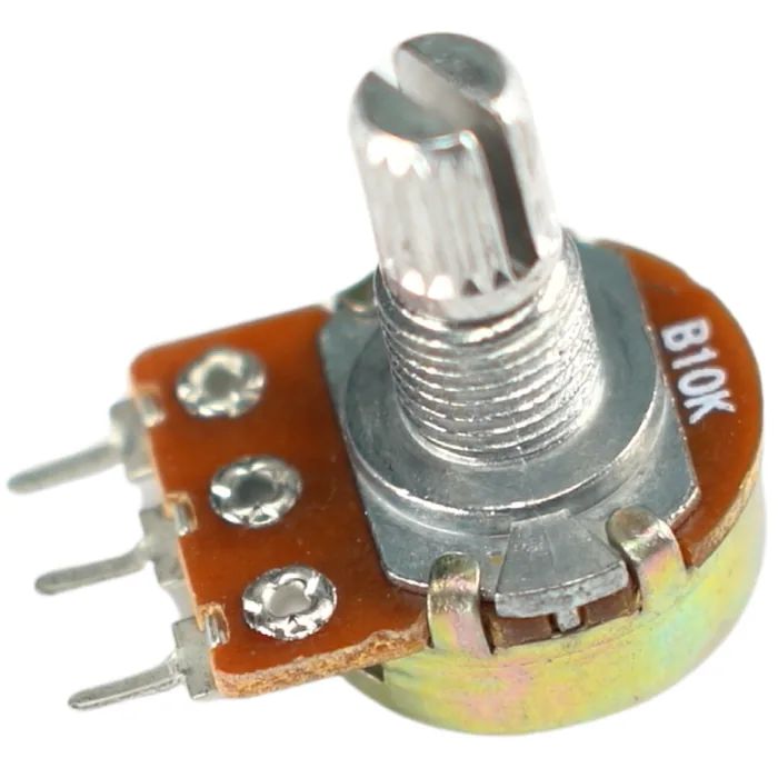
From the kit
10 kΩ potentiometer – the positioning knob in manual mode
analogRead() and map() – Part 5, controlling a servo – Part 7.
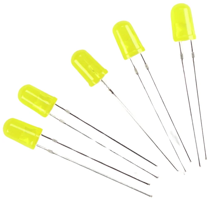
From the kit
Three LEDs – direction lights: left / stop / right
I suggest yellow / green / yellow, but any color will do. Polarity and digitalWrite() – Parts 4 and 5.
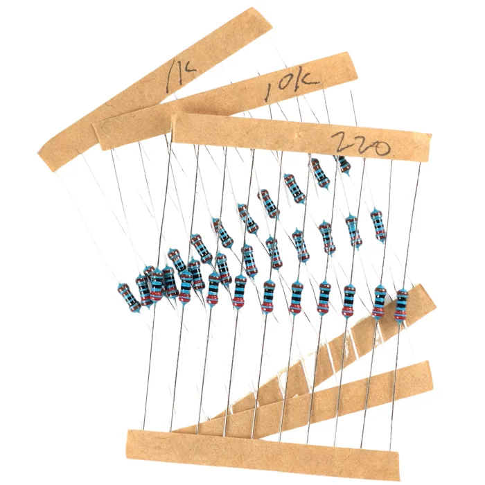
From the kit
Three 220 Ω resistors – one for each LED
Why an LED cannot work without a resistor – Parts 4 and 5.
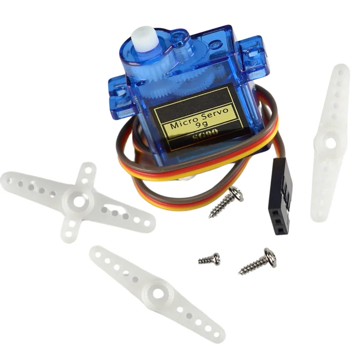
From the kit
SG90 servo – the rotating base of the arm
The Servo library, attach(), write() and power – Part 7.
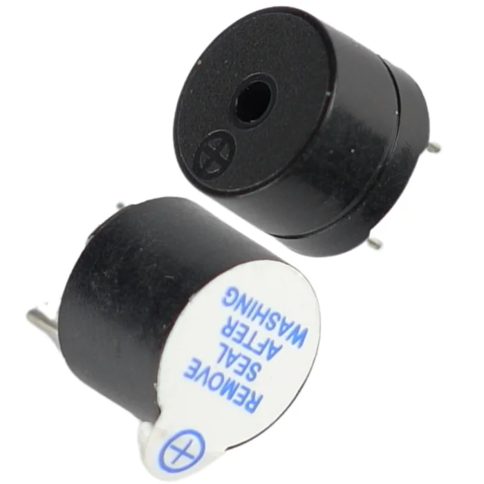
From the kit
Passive buzzer – the limit alarm
It has to be passive, because we use tone(). The difference between active and passive, and tone() / noTone() – Part 6.
03
Two modes: manual and automatic
One button, two behaviors of the whole device. This is the first program in the series that “remembers” what state it is in.
In manual mode the angle of the arm comes from the knob, exactly as in Part 7. In automatic mode the program itself adds a few degrees on every pass of the loop, and when it reaches 0° or 180°, it turns back. The arm travels back and forth without anyone touching the knob.
The button does the switching. Detecting a press follows the same pattern as in Parts 5 and 6: you compare the current reading with the previous one and react only at the moment when HIGH changes to LOW. This time, instead of turning on an LED, you flip the variable autoMode with !autoMode: now false, now true.
This one variable of type bool is what lets the program “know” what it should be doing at any moment. The rest of the loop only checks it: if (autoMode) { ... } else { ... }.
04
How we know which way the arm is moving
The servo does not tell the Arduino where it is. But the Arduino can work it out, by remembering where it was a moment ago.
In automatic mode it is simple: you set the direction yourself in the code. It is the variable autoDirection (+1 or -1). In manual mode it has to be worked out, and here is a trap.
The obvious idea: “compare the angle with the one from the previous pass of the loop”, as with the button in Parts 5–6. That will not work. The loop runs hundreds of times a second, and the reading from the potentiometer wobbles by a few units even when the knob is not moving. That wobble is bigger than the movement of the knob between two readings so close together. The program would “see” movement to the right one moment and to the left the next, and all three LEDs would shine at once.
The solution: compare the angle with the position from about half a second ago. The program saves it on every tenth pass of the loop. Over that much time real turning gives a clear change, and the wobble alone averages out. On top of that comes a dead zone: a difference smaller than 4° counts as “standing still”.
- the angle is clearly bigger than half a second ago → the arm is moving right → the “right” LED,
- clearly smaller → left → the “left” LED,
- almost the same → standing still → the “stop” LED.
When you turn the knob very slowly, the direction light may blink “stop” for a moment: the program has just refreshed its reference point. That is not a bug.
05
Building the circuit
The biggest circuit in this series, but with no new rules, only more of the same. Go row by row and check as you go.
What you need: the breadboard, the R3 board, the SG90 servo, the 10 kΩ potentiometer, a tact switch button, three LEDs, three 220 Ω resistors, three male-to-male jumper wires for the servo and about eight jumper wires for the rest.
| Part | Pin | Goes to | Note |
|---|---|---|---|
| Servo | brown/black wire | “–” rail (GND) | ground |
| Servo | red wire | “+” rail (5 V) | power |
| Servo | orange/yellow wire | pin 9 | angle signal |
| Potentiometer | first outer leg | “+” rail (5 V) | power for the divider |
| Potentiometer | wiper (middle leg) | A0 | analog reading |
| Potentiometer | second outer leg | “–” rail (GND) | ground for the divider |
| Button | leg 1 | D2 | in the code: INPUT_PULLUP |
| Button | leg 3 (diagonally opposite) | “–” rail (GND) | pressed = LOW |
| “Left” LED | anode through a 220 Ω resistor | pin 5 | cathode to “–” |
| “Stop” LED | anode through a 220 Ω resistor | pin 6 | cathode to “–” |
| “Right” LED | anode through a 220 Ω resistor | pin 7 | cathode to “–” |
| Passive buzzer | “+” (or the longer leg) | pin 8 | other leg to “–” |
  SERVO (base of the arm):
  pin 9 ── orange     5V ── red     GND ── brown

  POTENTIOMETER (position knob):       BUTTON (mode):
  5V  ──┤ outer leg                    D2 ──┤ button ├── GND
        │ wiper ──► A0
  GND ──┤ outer leg

  DIRECTION LEDS (each through 220 Ω):  BUZZER (limit alarm):
  pin 5 ──[ 220 Ω ]──►|── GND  (left)   pin 8 ──┤ buzzer ├── GND
  pin 6 ──[ 220 Ω ]──►|── GND  (stop)
  pin 7 ──[ 220 Ω ]──►|── GND  (right)
The LEDs and the buzzer go on pins 5–8, not 9–10. Those two are taken by the Servo library (you remember that from Part 7).
This is the whole control panel built on the breadboard:
Step-by-step assembly
Build the circuit on the breadboard
Loading the 3D view...
Power the rails of the breadboard
With one jumper wire connect the 5V pin of the R3 board to the “+” rail, with another the GND pin to the “–” rail.
Order of assembly:
- 1Power the rails of the breadboard: one jumper wire from the 5 V pin of the R3 board to the “+” rail, another from the GND pin to the “–” rail.
- 2Plug in the potentiometer: the outer legs to “+” and “–”, the middle one with a jumper wire to A0.
- 3Plug in the button straddling the groove: one leg to D2, the leg diagonally opposite to “–”.
- 4Plug in the three LEDs: the anode of each (the longer leg) through a 220 Ω resistor to pin 5, 6 and 7, the cathode of each to the “–” rail.
- 5Plug in the buzzer: “+” (or the longer leg) to pin 8, the other leg to “–”.
- 6Push three jumper wires into the plug of the servo: the brown one to “–”, the red one to “+”, the orange one straight into pin 9.
- 7Check everything once more. Only now plug in the USB cable.
- 8Attach a strip of cardboard or a little stick to the horn of the servo. That is your arm.
06
The program step by step
Lots of lines, little that is new. At each block we tell you which part you know it from.
#include <Servo.h>          // the library that controls a servo - you met it in Part 7

// --- Pins (assigned once for the whole program, that is why const int) ---
const int potPin    = A0;   // the wiper of the potentiometer - the knob that positions the arm
const int buttonPin = 2;    // the button - switches between manual and automatic mode
const int leftPin   = 5;    // indicator LED: the arm is moving left
const int stopPin   = 6;    // indicator LED: the arm is standing still
const int rightPin  = 7;    // indicator LED: the arm is moving right
const int buzzerPin = 8;    // the passive buzzer - the limit alarm

Servo arm;                  // an object of the Servo library - the "remote control" for our servo

// --- State variables: the program has to remember them between passes of the loop ---
bool autoMode = false;      // false = manual mode (the knob), true = automatic mode (the cruise)
int  previousState = HIGH;  // the state of the button in the previous pass; HIGH = released

int angle = 90;             // the current angle of the arm in degrees (0-180); it starts in the middle
int autoStep = 5;           // in auto mode the arm moves by this many degrees per pass
int autoDirection = 1;      // the direction of travel in auto mode: +1 = right, -1 = left

int referenceAngle = 90;    // the angle "a moment ago" - we compare with it to detect movement
int refreshCounter = 0;     // counts the passes of the loop until referenceAngle is refreshed

void setup() {                         // runs once, right after the power is turned on
  arm.attach(9);                       // tell the library that the servo sits on pin 9
  pinMode(buttonPin, INPUT_PULLUP);    // the button as an input with the pull-up resistor
  pinMode(leftPin,  OUTPUT);           // the three indicator LEDs as outputs...
  pinMode(stopPin,  OUTPUT);
  pinMode(rightPin, OUTPUT);
  pinMode(buzzerPin, OUTPUT);          // the buzzer as an output too
}

void loop() {                          // repeats forever, pass after pass
  // === 1. The button: detect a press and switch the mode (the pattern from Parts 5 and 6) ===
  int buttonState = digitalRead(buttonPin);          // read the button: LOW = pressed, HIGH = released
  if (buttonState == LOW && previousState == HIGH) { // it has just changed from released to pressed
    autoMode = !autoMode;                            // flip the mode: manual <-> automatic
    delay(20);                                       // a short pause for the contact bounce of the button
  }
  previousState = buttonState;                       // remember the state for the next pass

  // === 2. Work out the angle of the arm - differently in each mode ===
  if (autoMode) {
    angle = angle + autoDirection * autoStep;        // move the angle by one step in the current direction
    if (angle >= 180) { angle = 180; autoDirection = -1; } // reached 180 -> stop and turn back left
    if (angle <= 0)   { angle = 0;   autoDirection = 1; }  // reached 0   -> stop and turn back right
  } else {
    int reading = analogRead(potPin);                // measure the voltage on the wiper: a number 0-1023
    angle = map(reading, 0, 1023, 0, 180);           // convert the reading range to the angle range (as in Part 7)
  }

  arm.write(angle);                                  // send the angle to the servo - the arm will go there

  // === 3. Direction of movement -> which LED should shine ===
  // In auto mode we know the direction directly (autoDirection). In manual mode we have to work
  // it out: we compare the current angle with the position about half a second ago. Comparing with
  // the previous pass of the loop does not work - the wobble of the potentiometer reading is bigger
  // than the movement of the knob in such a short time, and all three LEDs would shine at once.
  int direction;                                     // -1 = left, 0 = standing still, +1 = right
  if (autoMode) {
    direction = autoDirection;                       // auto mode: we take the direction directly
  } else if (angle > referenceAngle + 4) {           // the angle is clearly bigger than a moment ago
    direction = 1;                                   //   -> the arm is moving right
  } else if (angle < referenceAngle - 4) {           // the angle is clearly smaller
    direction = -1;                                  //   -> the arm is moving left
  } else {                                           // a difference below 4 degrees (the dead zone)
    direction = 0;                                   //   -> we say that it is standing still
  }

  // Light the LED that matches the direction and turn the other two off.
  if (direction == 1) {
    digitalWrite(rightPin, HIGH);                    // "right" shines
    digitalWrite(leftPin,  LOW);
    digitalWrite(stopPin,  LOW);
  } else if (direction == -1) {
    digitalWrite(leftPin,  HIGH);                    // "left" shines
    digitalWrite(rightPin, LOW);
    digitalWrite(stopPin,  LOW);
  } else {
    digitalWrite(stopPin,  HIGH);                    // "stop" shines
    digitalWrite(leftPin,  LOW);
    digitalWrite(rightPin, LOW);
  }

  // Every 10 passes (~0.5 s with delay(50)) move the reference point to the current angle.
  refreshCounter = refreshCounter + 1;               // count this pass
  if (refreshCounter >= 10) {                        // have 10 passes added up?
    referenceAngle = angle;                          //   -> save the current position as the new reference
    refreshCounter = 0;                              //   -> and start counting from zero
  }

  // === 4. The limit alarm - only in manual mode (tone / noTone from Part 6) ===
  if (!autoMode && (angle <= 1 || angle >= 179)) {   // manual mode AND the arm at the very end
    tone(buzzerPin, 1500);                           //   -> play a 1500 Hz tone
  } else {
    noTone(buzzerPin);                               //   -> in every other case, silence
  }

  delay(50);   // a 50 ms pause -> the loop repeats about 20 times a second, in both modes
}
Write this program in your browser
Tutorial on the left, editor on the right. Build your code and flash it to the board in one click, with nothing to install.
| Instruction | What it does |
|---|---|
#include <Servo.h> + arm.attach(9) | connects the servo as the base of the arm (Where you know it from: Part 7) |
digitalRead + previousState + !autoMode | detects a press and switches the mode (Where you know it from: Parts 5 and 6) |
analogRead(potPin) + map(..., 0, 180) | the knob sets the angle in manual mode (Where you know it from: Part 7) |
angle + autoDirection * autoStep, turning back at 0 and 180 | sweeping by itself in automatic mode (Where you know it from: new in this part) |
angle versus referenceAngle (the position from ~0.5 s ago) plus a dead zone of 4° | detecting the direction of movement in manual mode (Where you know it from: “remember and compare” from Part 5, taken further) |
refreshCounter + if (refreshCounter >= 10) | refreshes the reference point once every 10 passes of the loop (Where you know it from: new in this part) |
delay(50) at the end of loop() | a steady pace of the loop in both modes – without it the direction LEDs flicker |
tone() / noTone() | the alarm when the arm is at the end of its range – only in manual mode (Where you know it from: Part 6) |
digitalWrite(leftPin, ...) | lights the matching direction light (Where you know it from: Parts 4 and 5) |
This program uses the library Servo 1.3.0. It is already added to the project in the editor next to the lesson.
Flash the code to the board through FlashESP.com, as in the earlier parts. After flashing, turn the knob: the arm follows it, a direction LED shines, and at the very ends the buzzer beeps. Press the button: the arm sets off on an automatic cruise back and forth, the buzzer falls silent, and the LEDs keep showing the direction. Press again: you are back to steering with the knob (the arm will jump to the position set by the knob).
Build checklist
Tick them off one by one. Your progress is saved in this browser.
0 / 16
Rules worth remembering
- 1
A servo under load gets its own power.
With an arm attached you load the SG90 more than in Part 7. If the board resets or the servo twitches, give it its own 4.8–6 V and connect the grounds.
- 2
Every LED has its own 220 Ω resistor.
Three LEDs without resistors are three burned-out LEDs. A resistor goes in series with each LED separately, not one shared by all.
- 3
The buzzer has to be passive.
An active one has a fixed tone, and
tone()will not change much about it. For the details go back to Part 6. - 4
With this many wires, rewire with the USB unplugged.
Pull out the cable, move the jumper wire, check the row, and only then plug it back in.
Projects
None of the projects below needs anything extra: they all build on the same circuit. They go from the easiest to the most ambitious.
- 1
Blinking direction lights
Easy- What you will use
- this circuit
- What you will learn
- making the direction LED blink instead of shining steadily – with
millis()or a counter of loop passes
- 2
Setting the pace of the automatic cycle
Easy- What you will use
- this circuit
- What you will learn
- letting the knob set
autoStepin automatic mode – one variable changes the speed of the cruise
- 3
A third mode: center
Medium- What you will use
- this circuit
- What you will learn
- moving the arm to 90° with a long press of the button – measuring how long the button is held down
- 4
Soft limits
Medium- What you will use
- this circuit
- What you will learn
- slowing the arm down near 0° and 180° instead of slamming into them at full speed – a changing
autoStepclose to the end
- 5
Teach and repeat
Challenging- What you will use
- this circuit
- What you will learn
- setting a position in manual mode and saving it with the button; the automatic mode then travels between two saved positions – like a real “teach pendant” panel
Summary
The section about control ends where each of its parts began: read the input, calculate, set the output. Part 5 connected an LED to it, Part 6 a buzzer, Part 7 a servo. And now everything at once, with a mode switch and direction lights, just like the panel of a real machine.
There was little that was new: one bool variable that holds the mode, and comparing the current angle with the position from a moment ago to detect the direction of movement (not from one pass of the loop ago: that is too close to tell anything). Both tricks will come back in later projects, from displays to games.