XXL Kit for Arduino · Movement
Part 7 Controlling a servo: a potentiometer and a servo
- Beginner
- Ages 8+
- about 45 min
In this part the potentiometer stops controlling something that shines or makes a sound. It starts to control movement. You will connect an SG90 servo and make its arm turn exactly to where you set the knob. Along the way you will meet the first library in this series and find out why this little motor can be fussy about its power.
Who is it for? For children and teenagers aged 8 and up, for teachers, and for adults who have done Parts 5 and 6 and want to see the same control pattern connected to something that physically moves.
01
The SG90 servo
An ordinary motor “spins and spins”. A servo is different: you tell it “go to 90 degrees”, and it travels there and holds the position.
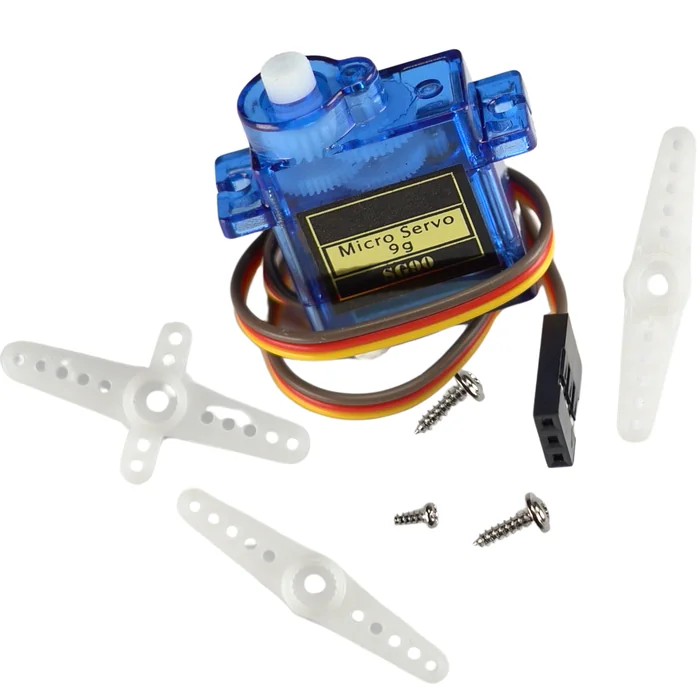
From the kit
Tower Pro SG90 servo
It turns to a set angle, not “round and round”. Inside it has a small motor, gears, control electronics and a position sensor. You give it an angle from 0° to 180°, and the servo travels there by itself and holds the position, even when something pushes it lightly.
The servo has three wires that come out in one flat cable:
| Wire color | Function | Where it goes |
|---|---|---|
| brown (or black) | ground | GND |
| red | power | 5 V |
| orange (or yellow) | signal – the angle command | a digital pin of the Arduino |
02
How an Arduino tells a servo where to go
Not “how much current” and not “how fast”. This time what counts is the length of the pulse. Luckily you do not have to measure it out by hand.
The servo listens for a short pulse repeated about 50 times a second. What matters is how long that pulse is: about 1 millisecond is one end position, about 2 milliseconds is the other, and 1.5 ms is the middle. If you had to time this yourself in the code, it would be tiring and easy to get wrong.
That is why we will use a library. A library is a ready-made piece of code that somebody wrote and shared so that you do not have to invent everything from scratch. The line #include <Servo.h> at the top of the program includes the library that handles servos. From then on you have simple commands: attach() (say which pin the servo is on) and write() (set an angle from 0 to 180). All the fuss with milliseconds happens underneath, without you.
This is already the third way of controlling an output in this series:
| Part | Command | What you set |
|---|---|---|
| 5 – LED | analogWrite(pin, 0–255) | how much time the pin is HIGH – brightness |
| 6 – buzzer | tone(pin, hertz) | how fast the pin switches – pitch of the sound |
| 7 – servo | servo.write(0–180) | the length of the pulse – angle of the arm |
03
Powering the servo
The servo is the first part in this series that can “eat” more current than a board powered from USB can give.
When the servo starts moving, especially fast or under load, it draws a lot of current for a fraction of a second. A small SG90 with nothing attached to its arm usually manages on power straight from the 5 V pin of the board, and in this part we will leave it at that. But if you notice any of these:
- the servo twitches, “buzzes” and does not hold its position calmly,
- the R3 board resets at the moment of movement (it goes off and comes back),
- the L LED on the board dims with every movement of the arm,
that is a sign that the servo needs its own power: a pack of 4 AA batteries (about 6 V) or a 5 V power supply. Then one iron rule applies: the ground (GND) of that power must be connected to the ground of the Arduino. Without a common ground the signal from the control pin has no reference point and the servo behaves randomly.
04
Reminder: the potentiometer
A part from Part 5, so here is only a refresher. The same connection, this time hooked up to a servo instead of an LED.
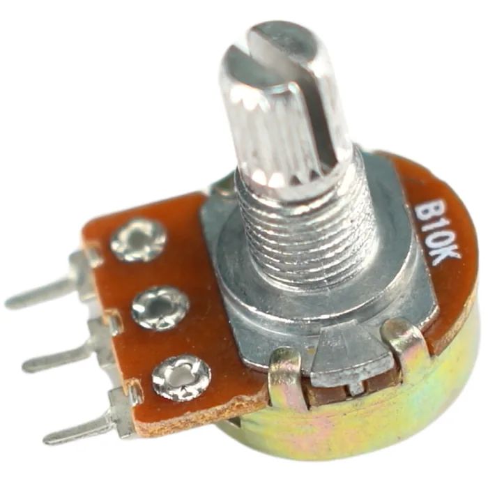
From the kit
10 kΩ potentiometer
An analog input. analogRead() returns a number 0–1023 that depends on where the knob is. Outer legs on 5 V and GND, middle leg (the wiper) on A0. The full explanation is in Part 5.
05
Building the circuit
The theory ends here. In a moment you will turn the knob and the servo's arm will follow it.
What you need: the breadboard, the R3 board, the SG90 servo, the 10 kΩ potentiometer, 3 male-to-male jumper wires for the servo, 3 male-to-male jumper wires for the potentiometer.
The servo ends in a plug with three sockets. Push three male-to-male jumper wires firmly into it and connect their other ends as the table says: two to the power rails of the breadboard, one to pin 9.
| Part | Pin | Goes to | Note |
|---|---|---|---|
| Servo | brown/black wire | “–” rail (GND) | ground |
| Servo | red wire | “+” rail (5 V) | power |
| Servo | orange/yellow wire | pin 9 | angle signal |
| Potentiometer | first outer leg | “+” rail (5 V) | power for the divider |
| Potentiometer | wiper (middle leg) | A0 | analog reading |
| Potentiometer | second outer leg | “–” rail (GND) | ground for the divider |
This is the circuit built on the breadboard:
Step-by-step assembly
Build the circuit on the breadboard
Loading the 3D view...
Power the rails of the breadboard
With one jumper wire connect the 5V pin of the R3 board to the “+” rail, with another the GND pin to the “–” rail.
Order of assembly:
- 1Power the rails of the breadboard: one jumper wire from the 5 V pin of the R3 board to the “+” rail, another from the GND pin to the “–” rail.
- 2Plug in the potentiometer with its three legs in three separate rows. Connect the outer legs with jumper wires, one to the “+” rail and the other to the “–” rail. Connect the middle leg with a jumper wire to pin A0.
- 3Push three jumper wires into the servo's plug. Connect the brown (or black) one to the “–” rail and the red one to the “+” rail, and plug the other end of the orange (or yellow) one straight into pin 9 of the R3 board.
- 4Check everything once more. Only now plug in the USB cable.
- 5Do not hold the servo's arm and do not turn it with your fingers. You change the angle only with the knob.
06
The program step by step
The circuit is ready, but it does not move. This code connects the knob to the arm.
#include <Servo.h>   // include the library that handles servos

const int potPin = A0;
Servo servo;          // a "remote control" for our servo

void setup() {
  servo.attach(9);    // the servo's signal wire is connected to pin 9
}

void loop() {
  int reading = analogRead(potPin);           // 0 - 1023
  int angle = map(reading, 0, 1023, 0, 180);  // convert to 0 - 180 degrees
  servo.write(angle);                         // set the servo to that angle
  delay(15);                                  // give the servo a moment to get there
}
Write this program in your browser
Tutorial on the left, editor on the right. Build your code and flash it to the board in one click, with nothing to install.
| Instruction | What it does |
|---|---|
#include <Servo.h> | includes the ready-made library that handles servos – without it the commands below do not exist |
Servo servo; | creates a “remote control” for one servo; you can choose any name instead of servo |
servo.attach(9) | tells the library that the servo's signal wire is connected to pin 9 |
analogRead(potPin) | returns a number 0–1023 that depends on where the knob is |
map(reading, 0, 1023, 0, 180) | converts the range of the potentiometer to the range of the servo's angle |
servo.write(angle) | sends the servo the command “go to this angle” |
delay(15) | a short pause so that the servo has time to start moving before the next command arrives |
This program uses the library Servo 1.3.0. It is already added to the project in the editor next to the lesson.
Flash the code to the board through FlashESP.com, as in the earlier parts. Servo is a standard Arduino library, so you do not have to install it separately. After flashing, turn the knob: the servo's arm follows it, from one end to the other. Let go of the knob: the servo holds the last position. If the servo twitches and “buzzes” instead of moving smoothly, go back to the section “Powering the servo” above.
Build checklist
Tick them off one by one. Your progress is saved in this browser.
0 / 13
Rules worth remembering
- 1
A servo under load gets its own power.
A small SG90 with nothing on its arm will usually manage from the 5 V pin. But if it trembles, if the board resets or if the arm carries any weight at all, give it its own 4.8–6 V.
- 2
Common ground.
When the servo has its own power, connect its GND to the GND of the Arduino. Otherwise the angle signal has no reference point and the servo “goes crazy”.
- 3
The
Servolibrary takes PWM away from pins 9 and 10.On the R3 board, after
attach()neither of these two pins will work withanalogWrite()any more. Move an LED you want to dim to pin 3, 5, 6 or 11. - 4
Do not turn the servo's arm with your fingers.
The gears are made of plastic, and their little teeth break easily if you force them. You change the angle with code, not by hand.
Projects
None of the projects below needs anything extra: everything is already in the kit. They go roughly from the easiest to the most ambitious.
- 1
A meter needle
Easy- What you will use
- the servo + the potentiometer + a paper arrow on the arm
- What you will learn
- turning the reading from the knob into an angle and reading an “analog” scale
- 2
A parking barrier
Easy- What you will use
- the servo + the potentiometer
- What you will learn
- using two target positions (0° and 90°) instead of smooth movement –
ifinstead ofmap()
- 3
Sweeping by itself
Medium- What you will use
- the servo alone
- What you will learn
- writing a
forloop that moves the arm 0° → 180° → 0° by itself
- 4
Calm movement
Medium- What you will use
- the servo + the potentiometer
- What you will learn
- averaging several
analogRead()readings so that the arm stops trembling, and narrowing the range to 20–160°
- 5
Joystick control
Challenging- What you will use
- the servo + the joystick module
- What you will learn
- seeing that a joystick is two potentiometers inside – it is enough to read one axis instead of a separate knob
Summary
This part closes the trio of “control something with a potentiometer”. Each time the skeleton was the same: read the knob, convert with map(), set the output. Only the output changed: brightness (analogWrite), the pitch of the sound (tone), and now the angle of the arm (servo.write). On the way you reached for a library for the first time: ready-made code that does the hard part, timing the pulses, for you.
You also met the first part that needs care with its power. A servo can draw more current than USB gives, and you will need to remember that again with the stepper motor and the relay.