XXL Kit for Arduino · Sound
Part 6 Controlling sound: a buzzer, a button and a potentiometer
- Beginner
- Ages 8+
- about 45 min
In this part the LED retires. Instead of it you control sound. You will learn the difference between an active and a passive buzzer, learn to make a tone of any frequency, and build a circuit in which the potentiometer changes the pitch of the sound and the button turns it on and off.
Who is it for? For children and teenagers aged 8 and up, for teachers, and for adults who have done Part 5 and want to connect the same pair of inputs (a button and a potentiometer) to something you can hear, not only see.
01
Active and passive buzzers
The same piece of plastic, two completely different ways of working. And only one of them lets you play a melody.
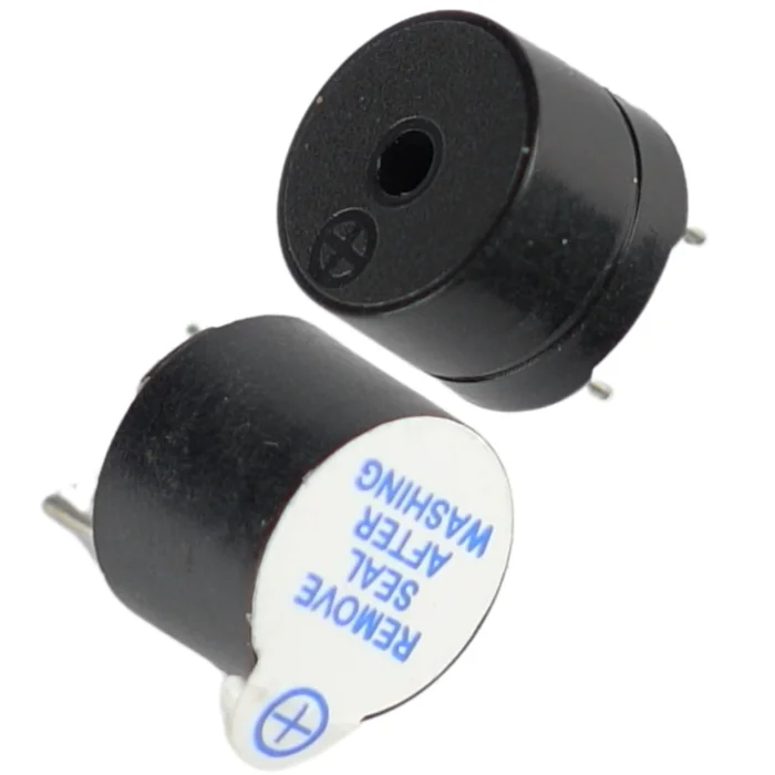
From the kit
Active and passive buzzer
It beeps by itself or plays on command. The active one has a built-in generator: you give it a voltage and it makes one steady sound all by itself. The passive one has no generator. It is you, through the program, who decides what sound comes out of it.
For this project you need the passive buzzer: only that one lets you change the pitch of the sound with the knob of the potentiometer. The active one can only “beep” or “be quiet”, with nothing in between.
How to tell them apart. Connect the buzzer for a moment straight to the 5 V and GND pins, with no code at all. If it beeps all by itself, it is the active one: it has a built-in generator. If you hear a quiet click at most, or nothing, it is the passive one: a steady voltage is not enough for it, it needs a changing signal.
02
How an Arduino makes sound
A speaker has no smooth “strength” like an LED. It has only pitch. The faster the membrane vibrates, the higher the sound you hear.
Inside, a buzzer is a tiny membrane that vibrates back and forth. The frequency of these vibrations, which means how many full movements the membrane makes in one second, is exactly the pitch of the sound, or its tone. The unit of frequency is the hertz (Hz): the bigger the number, the higher and thinner the sound.
To make such a signal, Arduino has a ready-made function: tone(pin, frequency). It turns a digital pin into a square wave of the given frequency: the pin switches between LOW and HIGH exactly as many times a second as the number of Hz you gave. The passive buzzer turns that into sound. To make it quiet, you call noTone(pin).
This is not the same as PWM from Part 5. analogWrite() changes how much time the pin spends HIGH, hence the brightness. tone() changes how fast the pin switches between the states, hence the pitch of the sound. That is why tone() works on any digital pin: it does not have to have the ~ sign.
| Function | What it sets | Effect |
|---|---|---|
analogWrite(pin, 0-255) | the share of time spent HIGH | brightness of the LED |
tone(pin, hertz) | the number of switches per second | pitch of the sound |
noTone(pin) | – | silence |
The human ear hears roughly 20–20,000 Hz, but the small buzzers from the kit sound best somewhere between 100 and 2000 Hz. That is the range we will use in the code.
03
Reminder: the button and the potentiometer
You already met both parts in Part 5, so here is only a quick refresher. The same connection, only hooked up to a buzzer instead of an LED.
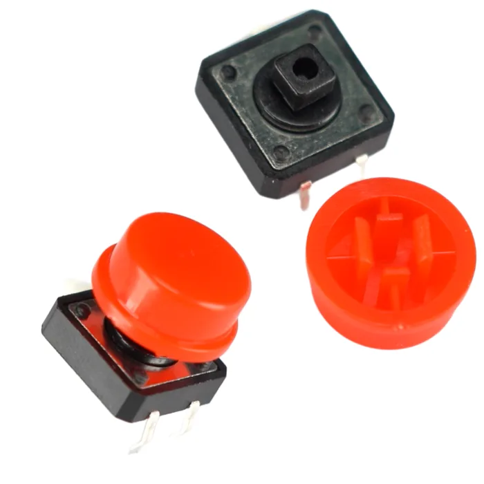
From the kit
Tact switch
A digital input. With INPUT_PULLUP a pressed button gives LOW, a released one HIGH. The full explanation is in Part 5.
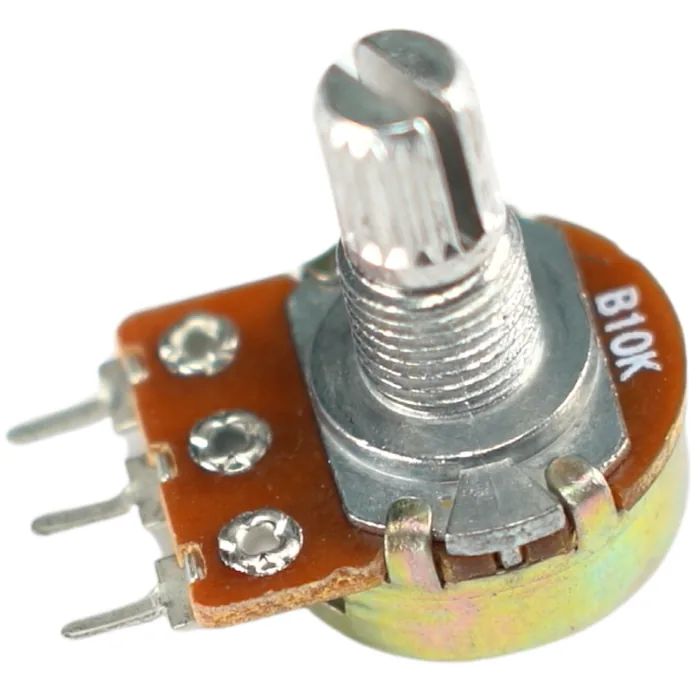
From the kit
10 kΩ potentiometer
An analog input. analogRead() returns a number 0–1023 that depends on where the knob is. The full explanation is in Part 5.
04
Building the circuit
The theory is over. In a moment you will turn the knob and hear the sound change its pitch.
What you need: the breadboard, the R3 board, the passive buzzer, the 10 kΩ potentiometer, a tact switch button, 5–6 male-to-male jumper wires. No resistors: unlike an LED, a buzzer limits its own current and does not need an extra one.
| Part | Leg / pin | Goes to | Note |
|---|---|---|---|
| Buzzer | “+” (or the longer leg) | pin 8 | signal from tone() |
| Buzzer | “–” | “–” rail (GND) | – |
| Potentiometer | first outer leg | “+” rail (5 V) | power for the divider |
| Potentiometer | wiper (middle leg) | A0 | analog reading |
| Potentiometer | second outer leg | “–” rail (GND) | ground for the divider |
| Button | leg 1 | D2 | in the code: INPUT_PULLUP |
| Button | leg 3 (diagonally opposite) | “–” rail (GND) | pressed button = LOW |
  BUZZER (sound):
  8 ──┤ buzzer ├── GND          “+” (or the longer leg) on the side of pin 8

  POTENTIOMETER (sets the pitch of the sound):
  5V  ──┤ outer leg
        │  10 kΩ potentiometer   wiper ──► A0
  GND ──┤ outer leg

  BUTTON (turns the sound on / off):
  D2 ──┤ button ├── GND         INPUT_PULLUP in the code, pressed = LOW
This is the same circuit built on the breadboard:
Step-by-step assembly
Build the circuit on the breadboard
Loading the 3D view...
Power the rails of the breadboard
With one jumper wire connect the 5V pin of the R3 board to the “+” rail, with another the GND pin to the “–” rail.
Order of assembly:
- 1Power the rails of the breadboard: one jumper wire from the 5 V pin of the R3 board to the “+” rail, another from the GND pin to the “–” rail.
- 2Plug in the potentiometer with its three legs in three separate rows. Connect the outer legs with jumper wires, one to the “+” rail and the other to the “–” rail. Connect the middle leg with a jumper wire to pin A0.
- 3Plug in the button straddling the groove in the middle of the breadboard. Connect one leg with a jumper wire to pin D2, and the leg diagonally opposite to the “–” rail (GND).
- 4Plug in the buzzer: connect the “+” leg (or the longer one) with a jumper wire to pin 8, and the other leg to the “–” rail (GND).
- 5Check everything once more. Only now plug in the USB cable.
05
The program step by step
The circuit is ready, but mute. This code teaches it to speak, or rather to beep on command.
const int buzzerPin = 8;    // the passive buzzer on any digital pin
const int potPin = A0;      // the potentiometer on an analog input
const int buttonPin = 2;    // the button on a digital input

bool soundOn = false;       // we start muted, the first press turns the sound on
int previousState = HIGH;   // the previous reading of the button (INPUT_PULLUP: released = HIGH)

void setup() {
  pinMode(buzzerPin, OUTPUT);
  pinMode(buttonPin, INPUT_PULLUP); // turns on the built-in pull-up resistor
}

void loop() {
  // 1. Read the button, with a simple guard against contact bounce
  int buttonState = digitalRead(buttonPin);
  if (buttonState == LOW && previousState == HIGH) { // it has just been pressed
    soundOn = !soundOn;                              // toggle: it was on -> now it is off
    delay(20);                                       // wait out the contact bounce
  }
  previousState = buttonState;

  // 2. Read the potentiometer and convert the reading to the audible range
  int reading = analogRead(potPin);                 // 0 - 1023
  int frequency = map(reading, 0, 1023, 100, 2000); // 100 - 2000 Hz

  // 3. Turn the buzzer on or mute it
  if (soundOn) {
    tone(buzzerPin, frequency);
  } else {
    noTone(buzzerPin);
  }
}
Write this program in your browser
Tutorial on the left, editor on the right. Build your code and flash it to the board in one click, with nothing to install.
| Instruction | What it does |
|---|---|
pinMode(buttonPin, INPUT_PULLUP) | sets the pin as an input and turns on the built-in pull-up resistor – a released button gives HIGH |
!soundOn | flips the value: true to false and back – one press toggles the state |
analogRead(potPin) | returns a number 0–1023 that matches the voltage on the wiper |
map(reading, 0, 1023, 100, 2000) | converts the range of the potentiometer to the range of audible frequencies |
tone(buzzerPin, frequency) | makes a wave of the given frequency on the pin – the buzzer starts to play |
noTone(buzzerPin) | stops the wave – the buzzer goes quiet |
Flash the code to the board through FlashESP.com, as in the earlier parts. Press the button: the buzzer starts to play. Turn the knob of the potentiometer: the sound smoothly changes pitch, from a low hum to a high squeal. Press the button again: silence, although the potentiometer is still set.
If the buzzer plays but the knob changes nothing, and the sound stays the same however you set it, you have probably connected the active buzzer, not the passive one. This is the best “live” test: unplug it with the power off and plug in the other one from the kit. The code itself does not change. It is the physical difference between the buzzers that decides whether the potentiometer has anything to control at all.
If something does not sound right, literally, go through the checklist below.
Build checklist
Tick them off one by one. Your progress is saved in this browser.
0 / 13
Rules worth remembering
- 1
A buzzer usually has polarity.
Check the “+” mark on the case or the longer leg. Connected backwards, it may not play at all.
- 2
tone()works on any digital pin.Unlike
analogWrite()from Part 5, it does not need a pin with the~sign. - 3
An input without
INPUT_PULLUP“floats”.The same rule as in Part 5: a button always goes with a pull-up resistor, built-in or your own.
- 4
We rewire the circuit with the power disconnected.
Pull out the USB cable, move the jumper wires, check once more and only then plug it back in.
Projects
None of the projects below needs anything extra: everything is already in the kit. They go roughly from the easiest to the most ambitious.
- 1
A simple beeper
Easy- What you will use
- the active buzzer + a button
- What you will learn
- using
digitalWrite()on a buzzer and seeing the difference between the active and the passive one in practice
- 2
A reversing beeper
Easy- What you will use
- the passive buzzer + the potentiometer
- What you will learn
- making the beeps faster the smaller the reading from the knob –
tone()in a loop withdelay()
- 3
A simple melody
Medium- What you will use
- the passive buzzer
- What you will learn
- playing a sequence of
tone()anddelay()from an array of frequencies – your first “piece” played by code
- 4
An alarm siren
Medium- What you will use
- the passive buzzer
- What you will learn
- switching back and forth between two fixed tones in a loop, without the potentiometer
- 5
An alarm with a countdown
Challenging- What you will use
- the passive buzzer + a button
- What you will learn
- using
millis()– the tone speeds up as time passes since the button was pressed
Summary
This part showed you the other side of the analog output. In Part 5 analogWrite() changed how much time the pin spends HIGH, hence the brightness. Here tone() changes how fast the pin switches between the states, hence the pitch of the sound. You also learned the difference between the active buzzer (it beeps by itself) and the passive one (it plays what you tell it to). And you have a simple test you can repeat to tell one from the other without reading anything on the case.
The same pattern, where a button turns something on and off and a potentiometer adjusts it, will come back many more times in this series, each time connected to something else.