XXL Kit for Arduino · Control
Part 5 First controls: a button and a potentiometer
- Beginner
- Ages 8+
- about 45 min
Until now the LED only followed orders from the code. In this part you add two inputs to the circuit, a button and a potentiometer, and you decide live when the LED shines and how brightly. On the way you will learn the difference between a digital and an analog signal, find out what PWM is, and write a program that reads the outside world instead of only controlling it.
Who is it for? For children and teenagers aged 8 and up, for teachers, and for adults who have built their first LED circuit in Part 4 and now want the circuit to react to a person.
01
Input versus output
Until now the conversation went one way: the code talked and the LED listened. Now the circuit starts listening to you.
In Part 4 pin D13 was set as OUTPUT: the R3 board put a voltage on it and the LED lit up. The same pin (and almost every other one) can work the other way round, as INPUT, which means an input. Then the board does not put out a voltage. It checks whether one is coming in from outside.
There are two kinds of input, and that is what this whole part is about:
| Role of the pin | Setting in the code | What it does | Example from the kit |
|---|---|---|---|
| Output | pinMode(pin, OUTPUT) | puts out 0 V or 5 V | LED, buzzer |
| Digital input | pinMode(pin, INPUT_PULLUP) | reads: is there a voltage or not | button, vibration sensor |
| Analog input | nothing to set | reads a voltage from 0 to 5 V as a number 0–1023 | potentiometer, photoresistor |
A button is a digital input: it knows only two states. A potentiometer is an analog input: it gives a smooth value. In this project you will use both at once.
02
The tact switch button
The simplest input there is: pressed or not. And it can still drive a beginner up the wall.
From the kit
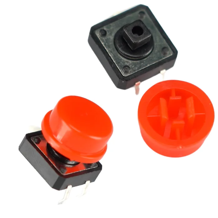
Tact switch – a momentary button
It works only while you hold it. When you let go, it returns to where it started. It has four legs, but they are two pairs joined for good inside the case. Pressing the button connects one pair to the other.
The two legs of one pair are joined by metal inside the button, so they do not have to land in the same row. Each leg goes into its own row of five holes, and that is where you plug in the jumper wire.
The groove down the middle of the breadboard splits it into two separate halves. Plug the button in across the groove (straddling it): one pair of legs lands on one side, the other pair on the other side. Until you press, the groove keeps the two pairs apart. Pressing connects them. A button turned by 90° puts legs from two different pairs into one row and is connected all the time: the circuit behaves as if somebody were holding the button down. If that happens, turn the button by 90°.
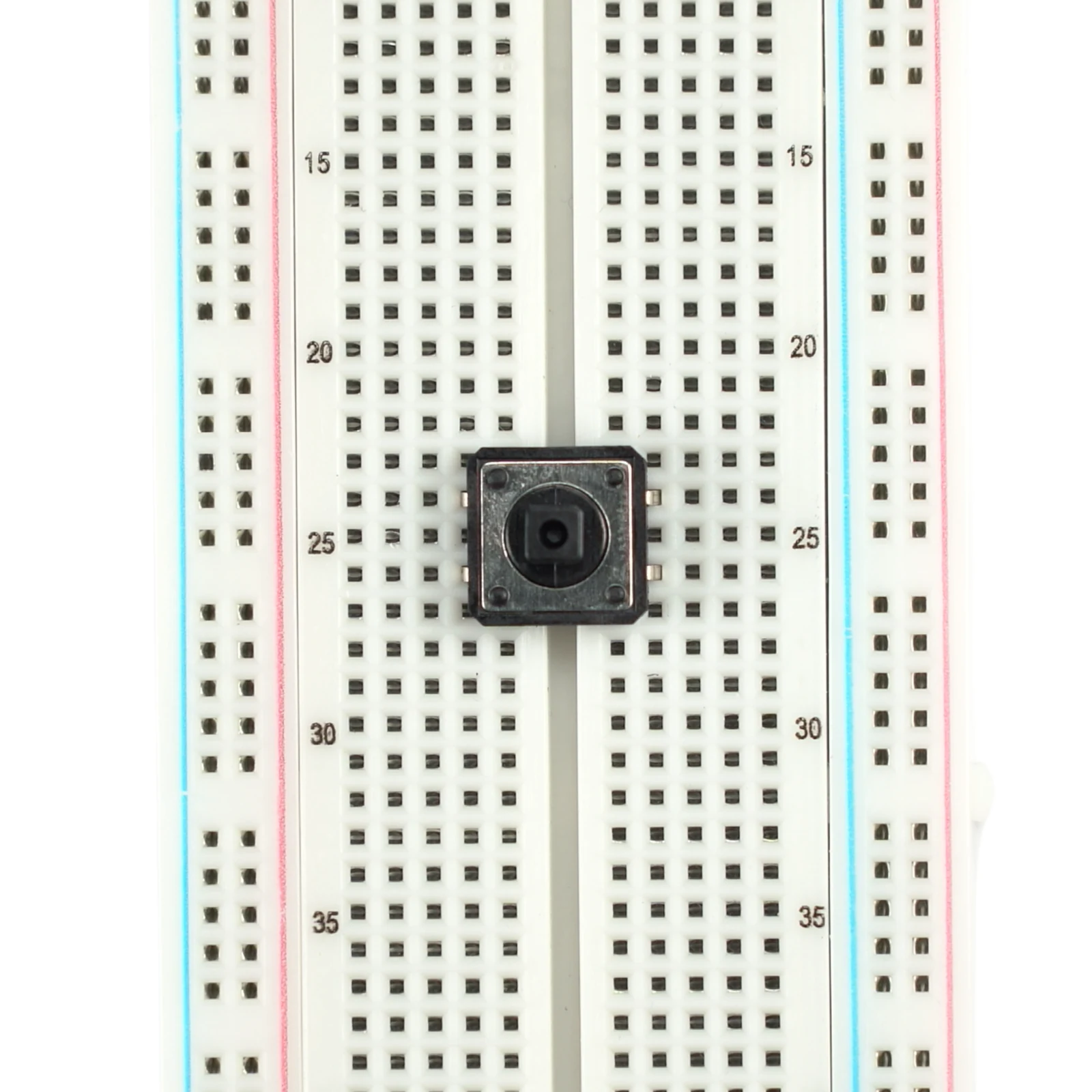
The connection in this circuit: one leg to D2, the leg diagonally opposite to GND.
The caps (5 in the kit) are just little hats pushed onto the stem. They make pressing easier and change nothing in the connections.
03
The pull-up resistor and INPUT_PULLUP
An input with nothing connected does not show “0”. It shows random noise: sometimes HIGH, sometimes LOW.
When the button is released, the input pin is not connected to anything. It “hangs in the air” (engineers say it is floating). It then picks up interference from its surroundings, and digitalRead() returns HIGH or LOW at random. The program becomes unpredictable.
The cure is a resistor that pulls the pin to a known state when the button is not pressed:
- A pull-up resistor connects the pin to 5 V. The pin is HIGH by default, and pressing the button pulls it down to GND, which means LOW.
- A pull-down resistor connects the pin to GND. The pin is LOW by default, and pressing the button lifts it to HIGH.
The good news: the ATmega328 chip has such pull-up resistors built in. You turn one on with a single word, pinMode(pin, INPUT_PULLUP), and you do not have to plug in a resistor of your own for the button. The price of this comfort: the logic is turned upside down. A pressed button is LOW, a released one is HIGH. In this series we use INPUT_PULLUP wherever we can: fewer wires and fewer chances to make a mistake.
04
The potentiometer
A button knows only two words. A potentiometer speaks in whole sentences: every value from zero to the maximum.
From the kit
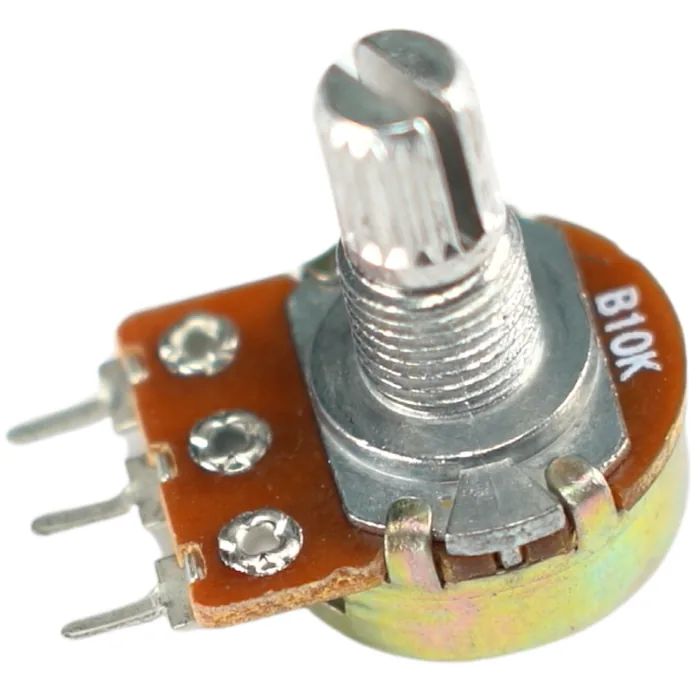
10 kΩ potentiometer
A resistor with a moving wiper. When you turn the knob, you move the wiper along the resistive track and change the voltage on the middle leg, smoothly, from 0 V to 5 V. It is the simplest way to tell a circuit “how much” instead of only “yes or no”.
The potentiometer has three legs: two outer ones and a middle one (the wiper).
| Leg of the potentiometer | Where it goes | What it is for |
|---|---|---|
| First outer leg | 5 V | power for the voltage divider |
| Middle leg (wiper) | A0 | the point where we read the voltage |
| Second outer leg | GND | ground for the voltage divider |
The instruction analogRead(A0) turns the voltage from the wiper into a whole number 0–1023 (the converter in the ATmega328 is 10-bit). 0 V gives the value 0, 5 V gives 1023, and the knob in the middle gives about 512.
The potentiometer does not stand in the way of the current to the LED. It is plugged in separately, as a voltage divider. Its only job is to put a voltage on A0 that depends on where the knob is, and the current that flows through it is tiny. The program decides how bright the LED is: it reads the number from A0 and puts PWM on pin ~9. The knob and the LED are connected only in the code.
You can also build a dimmer without a microcontroller, by putting the potentiometer in series with the LED so that turning it limits the current directly. In this series we do it differently, because: you will connect every sensor in the kit the same way (none of them can stand in series with an actuator), a 10 kΩ potentiometer in series with an LED dims smoothly only over a narrow slice of its turn, and in the program you can also use the value from A0 for a threshold or a switch.
You cannot “burn” the outer legs by swapping them, but swapping 5 V and GND reverses the direction: turning right will then make the value smaller instead of bigger. If that bothers you, simply swap those two wires.
05
Digital versus analog
An LED cannot shine “halfway”. And yet in a moment it will. The whole trick is called PWM.
Digital: a pin knows two states, LOW (0 V) and HIGH (5 V). That is what digitalRead() and digitalWrite() are for.
Analog on an input: analogRead() really measures the voltage and returns a number 0–1023.
Analog on an output: there is a catch. A pin cannot put out a real “half voltage”. Instead it blinks very fast, hundreds of times a second, part of the time HIGH and the rest LOW. The bigger the share of HIGH, the brighter the LED shines, because the eye sees the average. This method is called PWM (Pulse Width Modulation).
The instruction analogWrite(pin, value) takes a value 0–255: 0 is the LED off, 255 is full brightness, 127 is about half.
PWM works only on the pins marked on the board with the ~ sign: 3, 5, 6, 9, 10 and 11. An LED whose brightness you want to control has to sit on one of them. In this project we will use pin ~9.
| Function | Range | Direction | What we use it for here |
|---|---|---|---|
digitalRead() | LOW / HIGH | input | reading the button |
digitalWrite() | LOW / HIGH | output | LED on/off |
analogRead() | 0–1023 | input | reading the potentiometer |
analogWrite() | 0–255 (PWM) | output | brightness of the LED |
One problem is left: analogRead() gives 0–1023, and analogWrite() wants 0–255. The instruction map(reading, 0, 1023, 0, 255) does the conversion: it takes a number from one range and scales it to the other. You can also simply divide the reading by 4.
06
Building the circuit
The theory is over. In a moment you will turn the knob and the LED will obey.
What you need: the breadboard, the R3 board, one LED (any color), one 220 Ω resistor, the 10 kΩ potentiometer, a tact switch button, 6–7 male-to-male jumper wires.
You have seen the button and the potentiometer above. That leaves two parts from Part 4 that come back here:
From the kit
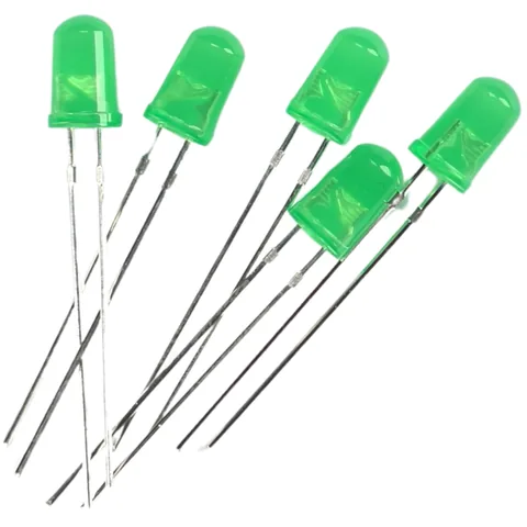
LED (any color)
It shines only one way round. The longer leg is the anode (plus), the shorter one is the cathode (minus). Plugged in backwards it will not light up, and that does not mean it is broken.
From the kit
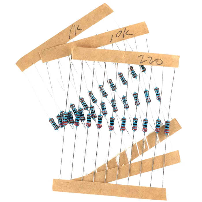
220 Ω resistor
A current limiter. It stays with the LED even when PWM controls the brightness. Without it the LED burns out in a second.
| Part | Leg / pin | Goes to | Note |
|---|---|---|---|
| Potentiometer | first outer leg | “+” rail (5 V) | power for the divider |
| Potentiometer | wiper (middle leg) | A0 | analog reading |
| Potentiometer | second outer leg | “–” rail (GND) | ground for the divider |
| Button | leg 1 | D2 | in the code: INPUT_PULLUP |
| Button | leg 3 (diagonally opposite) | “–” rail (GND) | pressed button = LOW |
| 220 Ω resistor | one end | pin ~9 | a PWM pin (~) |
| 220 Ω resistor | other end | the row with the LED's anode | limits the LED's current |
| LED | anode (longer leg) | the row with the resistor | plus side |
| LED | cathode (shorter leg) | “–” rail (GND) | minus side |
  LED (brightness):
  ~9 ──[ 220 Ω ]──►|── GND
                  LED        anode (longer leg) on the resistor's side

  POTENTIOMETER (sets the brightness):
  5V  ──┤ outer leg
        │  10 kΩ potentiometer   wiper ──► A0
  GND ──┤ outer leg

  BUTTON (turns on / off):
  D2 ──┤ button ├── GND         INPUT_PULLUP in the code, pressed = LOW
Step-by-step assembly
Build the circuit on the breadboard
Loading the 3D view...
Power the rails of the breadboard
With one jumper wire connect the 5V pin of the R3 board to the “+” rail, with another the GND pin to the “–” rail.
07
The program step by step
The circuit is ready, but deaf. This code gives it hearing.
const int ledPin = 9;       // the LED on a PWM output (~9)
const int potPin = A0;      // the potentiometer on an analog input
const int buttonPin = 2;    // the button on a digital input

bool ledOn = true;          // should the LED shine at all
int previousState = HIGH;   // the previous reading of the button (INPUT_PULLUP: released = HIGH)

void setup() {
  pinMode(ledPin, OUTPUT);
  pinMode(buttonPin, INPUT_PULLUP); // turns on the built-in pull-up resistor
}

void loop() {
  // 1. Read the button, with a simple guard against contact bounce
  int buttonState = digitalRead(buttonPin);
  if (buttonState == LOW && previousState == HIGH) { // it has just been pressed
    ledOn = !ledOn;                                  // toggle: it was on -> now it is off
    delay(20);                                       // wait out the contact bounce
  }
  previousState = buttonState;

  // 2. Read the potentiometer and convert the reading to the PWM range
  int reading = analogRead(potPin);               // 0 - 1023
  int brightness = map(reading, 0, 1023, 0, 255); // 0 - 255

  // 3. Set the LED
  if (ledOn) {
    analogWrite(ledPin, brightness);
  } else {
    analogWrite(ledPin, 0);
  }
}
Write this program in your browser
Tutorial on the left, editor on the right. Build your code and flash it to the board in one click, with nothing to install.
| Instruction | What it does |
|---|---|
pinMode(buttonPin, INPUT_PULLUP) | sets the pin as an input and turns on the built-in pull-up resistor – a released button gives HIGH |
digitalRead(buttonPin) | checks the state of the button: LOW is pressed, HIGH is released |
!ledOn | flips the value: true to false and back – one press toggles the state |
analogRead(potPin) | returns a number 0–1023 that matches the voltage 0–5 V on the wiper |
map(reading, 0, 1023, 0, 255) | converts the range of the potentiometer to the range of PWM brightness |
analogWrite(ledPin, brightness) | sets the brightness of the LED: 0 is off, 255 is full |
After flashing, turn the knob of the potentiometer: the LED smoothly gets brighter and dimmer. Press the button: the LED goes out completely, although the potentiometer is still set. Press again: it returns to the brightness set by the knob. If something is not right, go through the checklist below.
Build checklist
Tick them off one by one. Your progress is saved in this browser.
0 / 15
Rules worth remembering
- 1
An input without a pull-up resistor “floats”.
A released button connected straight to a pin gives random readings. Use
INPUT_PULLUP, and remember that a pressed button is thenLOW, notHIGH. - 2
analogWrite()works only on pins with a~.On the R3 board these are pins 3, 5, 6, 9, 10 and 11. On the others
analogWrite()behaves like plain on/off. - 3
analogReadspeaks 0–1023,analogWritelistens to 0–255.These are two different ranges. Between them there is always
map()or a division by 4. - 4
An LED still needs its resistor.
You control the brightness, but the 220 Ω resistor stays with the LED: PWM does not protect the LED from too much current.
Projects
None of the projects below needs anything extra: everything is already in the kit. They go roughly from the easiest to the most ambitious.
- 1
A dimmer for a lamp
Easy- What you will use
- the potentiometer + 1 LED
- What you will learn
- reading with
analogReadand scaling a range withmap()
- 2
A night light with a switch
Easy- What you will use
- the circuit from this part
- What you will learn
- combining a digital and an analog input in one program
- 3
Blinking controlled by the knob
Medium- What you will use
- the potentiometer + 1 LED
- What you will learn
- using a reading as the argument of
delay()– the knob sets the tempo
- 4
A bar indicator
Medium- What you will use
- the potentiometer + a green, a yellow and a red LED
- What you will learn
- thresholds: which LED lights up at which reading
- 5
A smooth fade between two LEDs
Medium- What you will use
- the potentiometer + a green and a red LED + two 220 Ω resistors
- What you will learn
- driving two PWM outputs from one reading – one LED fades out (
255 - x), the other gets brighter
Summary
This part introduced an idea that comes back in every later part of the series: the input. The button showed you a digital signal (LOW or HIGH) and the problem of a floating input, which INPUT_PULLUP solves. The potentiometer showed you an analog signal: a smooth number 0–1023 from analogRead(). On the way you met PWM and analogWrite(), the way a digital pin pretends to give a smooth voltage, and map(), which joins the two ranges.
From now on your circuit does not just work – it reacts. The pattern “read the input, calculate, set the output” will come back with the buzzer, the servo and every sensor in the kit.