XXL Kit for Arduino · First circuit
Part 4 How to connect parts to an Arduino
- Beginner
- Ages 8+
- about 40 min
In this part you will build your first real circuit: a breadboard, an LED, a resistor and a few jumper wires. At the end you will flash your first program to the R3 board and watch the LED start blinking at your command. This is the most important part of the series: everything you learn later only builds on the same rules.
Who is it for? For children and teenagers aged 8 and up, for teachers, and for adults who already have the kit from Part 1 and want to unpack it for good at last.
01
The breadboard: how it works
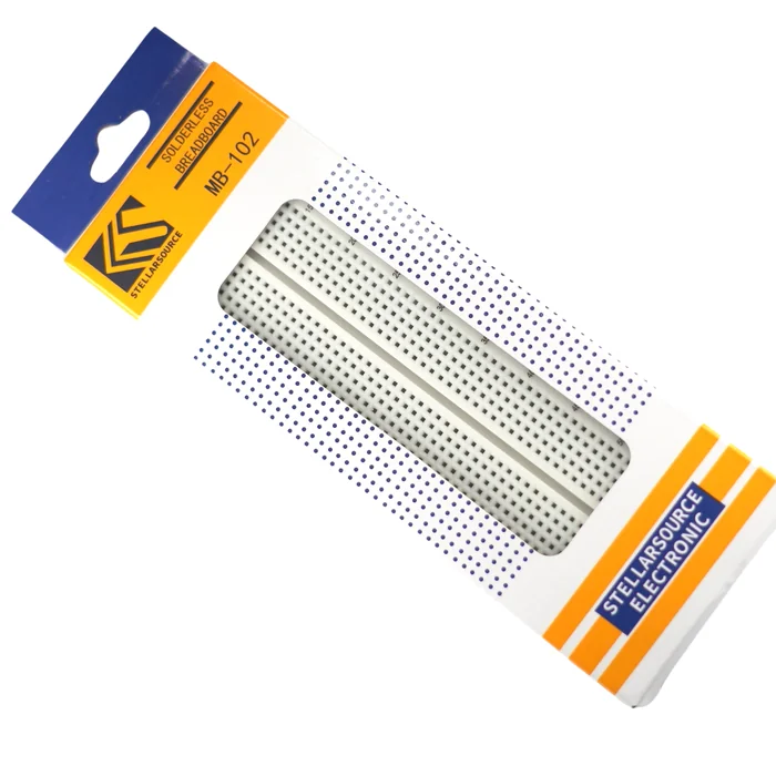
From the kit
830-point prototyping breadboard
The holes are not random. Under the plastic case sit metal clips that join whole groups of holes together. You push the leg of a part into one hole, and electrically it “appears” in all the other holes of the same group too.
At first glance it is a plastic slab with hundreds of holes, but its inner structure is very logical. Here are three things you need to know about it.
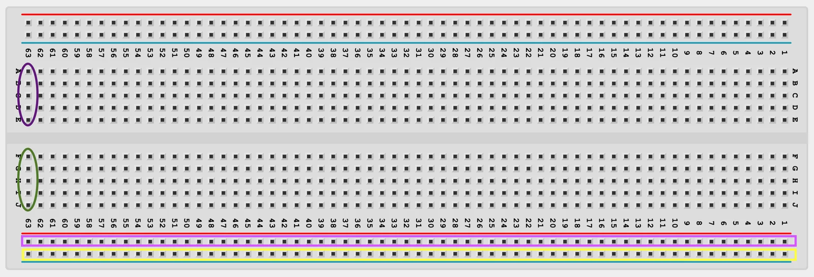
1. Power rails: the “+” and “–” lines
They run along the sides of the breadboard and are usually marked in red (plus) and blue (minus). They make it easy to spread power evenly to the whole circuit.
- Vertically: all the holes in one rail are connected to each other along the whole length of the breadboard.
- You use them to bring in the voltage from the Arduino and pass it on to the individual components.
In cheaper breadboards the middle groove sometimes cuts through the power rails too, not only the working area. If something does not work even though your wiring matches the diagram, check this first, with a multimeter or a continuity test.
2. The working area: the heart of the breadboard
This is the central area where we mount most components. It is divided into two halves, separated by a groove running down the middle of the breadboard (in the photo above, the purple loop and the green loop each show one such group of holes).
- Horizontally: every row of five holes (for example A1–E1) is connected inside.
- The groove in the middle lets you plug in chips without the risk of a short circuit between their legs.
Thanks to this you can test different versions of a circuit comfortably and safely, change them on the fly and react quickly to mistakes.
3. Letters and numbers
Breadboards are labeled like a table: letters across (A–J) and numbers down (1–30 or more, depending on the model). This makes it easier to describe connections and to find a particular point in the circuit.
02
Jumper wires: how they differ
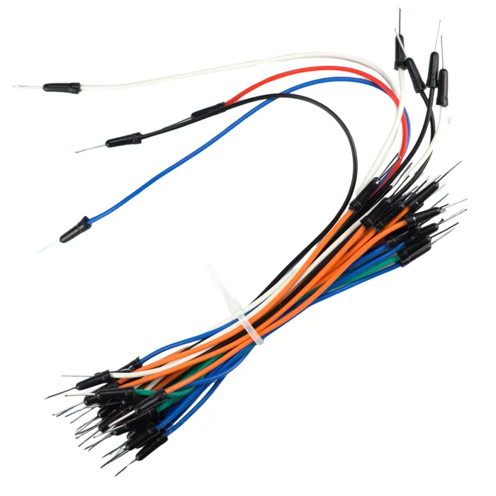
From the kit
Male-to-male jumper wires (65 pcs)
A stiff pin on both ends. The basic type. They connect holes on the breadboard to each other, and the breadboard to the pins of the R3 board.
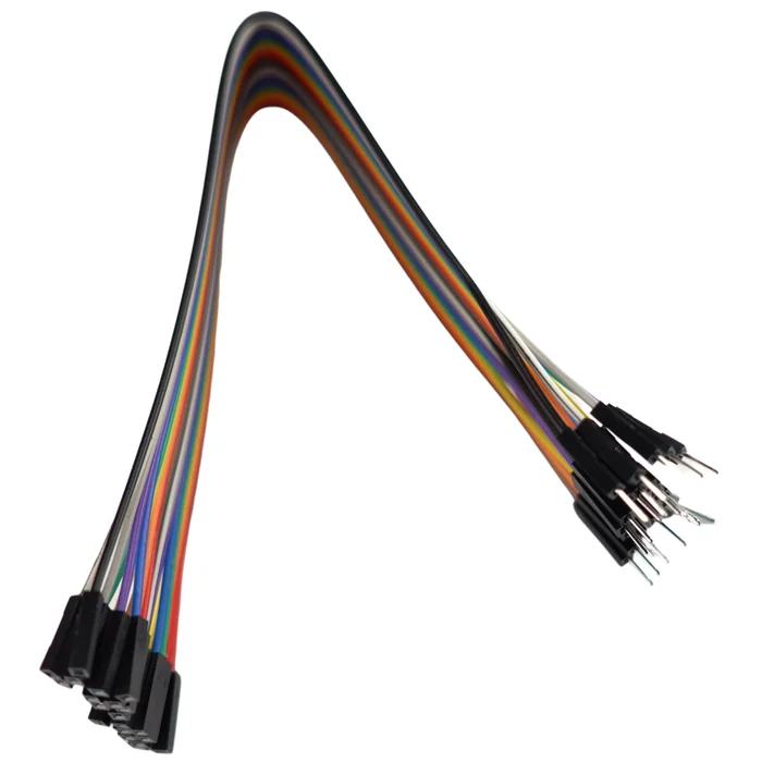
From the kit
Female-to-male jumper wires (10 pcs)
A socket on one end. They come in handy where a module already has pins of its own sticking out (sensors, displays). You push the socket straight onto the module's pin, without plugging the module into the breadboard.
In this part male-to-male jumper wires are all you need. The female-to-male ones will come back when you start connecting ready-made modules in later parts. There is also a third type, female-to-female, which you will not find in this kit. It connects two modules with pins sticking out directly to each other, with no breadboard in between.
03
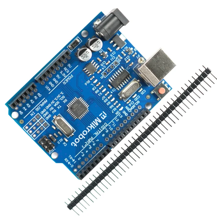
ATmega328: the brain of the Arduino
If the breadboard is a building site and the jumper wires are the roads, then the ATmega328 is the architect and the site manager in one. It decides what happens in your project.
From the kit
ATmega328 – a microcontroller
A miniature computer without an operating system. Unlike a computer or a phone, it does not run many programs at once. It runs only your code, line by line, starting over every time the power is turned on.
After flashing, the microcontroller keeps the program in its own memory for good. You can disconnect the board from the computer and power it from a 9 V battery: the program will still run, with no computer anywhere near.
The most important numbers worth knowing:
| Parameter | Value | What it is good for |
|---|---|---|
| Flash memory | 32 KB | this is where your program fits |
| EEPROM memory | 1 KB | permanent storage for data that survives the power being disconnected |
| RAM memory | 2 KB | room for variables while the program is running |
| Digital I/O pins | 23 | inputs or outputs – you decide in the code which they will be |
| Analog inputs (ADC) | 6 | reading sensors that give a continuous value, not only 0/1 |
| Communication interfaces | UART, SPI, I2C | ready-made “languages” the microcontroller uses to talk to other chips – you will meet them with the modules that need them |
04
The LED and the resistor
These two parts always come together. Remember this pair once and you will save yourself a burnt LED in every later project of this series.
From the kit
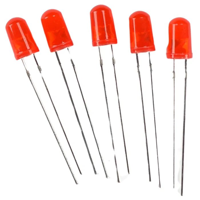
LED
It shines only one way round. It has two legs of different lengths: the longer one is the anode (plus), the shorter one is the cathode (minus). If the LED does not light up after you connect it, first check whether it is in backwards. That does not mean it is broken.
From the kit
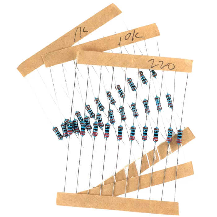
220 Ω resistor
A current limiter, not a decoration. Without it too much current will flow through the LED and you will simply burn it out. A second is usually enough. The 220 Ω resistor is a standard value that safely limits the current supplied by an Arduino pin.
Why exactly 220 Ω? An Arduino pin gives 5 V, the LED “uses up” about 2 V of that, and a safe current for a small LED is about 15–20 mA. The rest of the voltage has to go somewhere, and that is exactly the resistor's job.
05
Building your first circuit
The theory ends and the electronics begins. In a moment you will light your first LED with your own hands.
What you need: the breadboard, the R3 board, one LED, one 220 Ω resistor, two male-to-male jumper wires.
| Pin | Function | Board pin |
|---|---|---|
| One leg of the 220 Ω resistor | limits the current flowing to the LED | the row connected by a jumper wire to pin D13 |
| The other leg of the resistor | passes the limited current on | the same row as the LED's anode |
| Anode of the LED (longer leg) | the plus of the LED | the row connected to the resistor |
| Cathode of the LED (shorter leg) | the minus of the LED | the row connected by a jumper wire to GND |
Step-by-step assembly
Build the circuit on the breadboard
Loading the 3D view...
Plug in the 220 Ω resistor
One end in a free row on the breadboard, the other end in another free row.
06
Your first program
A circuit without a program is deaf. The R3 board does not know yet that it is supposed to light anything.
You write the code of this series and flash it to the R3 board in the browser, on the FlashESP.com platform, the same one you got to know in Part 2. FlashESP programs not only ESP boards but also the R3 board from this kit, so you do not install any program on your computer.
- 1Connect the R3 board to the computer with the USB A-B cable from the kit. The power light on the board comes on.
- 2Open this part on a computer, in Google Chrome or Microsoft Edge, and switch it to Code mode. On the right you see the editor with the starter code.
- 3Complete the code following the comments. The finished program is below: in Code mode you reveal it with the “Show the code” button.
- 4Click Build & flash.
- 5The first time you flash, the browser shows a small window with a list of ports. Choose the board (the R3 board with the CH340 chip usually has “USB Serial” or “CH340” in its name, and on Windows also a port number such as COM3) and click “Connect”.
- 6Wait while FlashESP saves, builds and flashes the program: a progress bar shows what is happening. Meanwhile the TX and RX lights on the board blink. Do not unplug the cable then.
- 7When the green message “Done. Your program is running on the board.” appears below the editor, look at the LED.
If something goes wrong, FlashESP says below the editor what happened and suggests what to check. The most common problems:
- The “Build & flash” button is turned off: the page is open on a phone, a tablet or in a browser without Web Serial (such as Firefox or Safari). Switch to a computer with Chrome or Edge.
- The board is not in the list of ports: check that the USB cable carries data (a charge-only cable is the most common cause) and that the power light on the board is on. If that does not help, the computer is missing the driver for the CH340 chip: install it following a separate step-by-step guide. You also find links to the driver in the “Serial Monitor” tab below the editor, under “Can't connect?”.
- “The board is not answering”: close other programs that may be using the port (such as the Arduino IDE), check that you chose the right port, unplug the board, plug it back in and try again.
- “The program did not build”: this is a mistake in the code, not in the board. Click the error in the list, and the editor takes you to the line with the problem.
const int ledPin = 13; // the number of the pin the LED is connected to

void setup() {
  pinMode(ledPin, OUTPUT); // set pin D13 as an output
}

void loop() {
  digitalWrite(ledPin, HIGH); // turn the LED on
  delay(500);                 // wait half a second
  digitalWrite(ledPin, LOW);  // turn the LED off
  delay(500);                 // wait half a second
}
Write this program in your browser
Tutorial on the left, editor on the right. Build your code and flash it to the board in one click, with nothing to install.
| Instruction | What it does |
|---|---|
pinMode(ledPin, OUTPUT) | sets pin D13 as an output – from now on it can put out a voltage |
digitalWrite(ledPin, HIGH) | turns on the voltage on the pin – the LED lights up |
digitalWrite(ledPin, LOW) | turns off the voltage – the LED goes out |
delay(500) | stops the program for 500 milliseconds, which is half a second |
After flashing, the LED should start blinking evenly: half a second on, half a second off. Notice that the small LED marked L on the R3 board itself blinks together with your external LED. That is no accident: pin D13 has a built-in LED like this connected to it for good. That is exactly why we chose this pin for the first test. If nothing happens, go through the checklist below.
Build checklist
Tick them off one by one. Your progress is saved in this browser.
0 / 11
Rules worth remembering
- 1
An LED always needs a resistor.
Usually 220 Ω. Without it the LED shines really beautifully – exactly once.
- 2
An LED has a right way round.
The longer leg is the plus (the anode). Plugged in backwards it simply will not light up, and that does not mean it is broken.
- 3
We rewire the circuit with the power disconnected.
Pull out the USB cable, move the jumper wires, check once more, and only then plug it back in.
Projects
None of the variants below needs anything extra: you already have everything in the kit.
- 1
Faster and slower blinking
Easy- What you will use
- the same circuit
- What you will learn
- seeing how
delay()changes the rhythm of the program
- 2
Moving the LED to another pin
Easy- What you will use
- the same circuit moved to pin D8, with
ledPinchanged in the code - What you will learn
- seeing that the built-in LED L blinks independently of yours, because it is connected to D13 for good
- 3
Two LEDs blinking in turn
Medium- What you will use
- a second LED, a second 220 Ω resistor, two jumper wires
- What you will learn
- connecting several independent circuits on one breadboard
- 4
A simple traffic light
Medium- What you will use
- a red, a yellow and a green LED, three 220 Ω resistors
- What you will learn
- controlling a sequence of events in time
Summary
The breadboard, jumper wires, the LED and the resistor are four things you will meet in almost every later part of this series. Now that you know how the holes on the breadboard are connected, how to spot the plus of an LED and what the resistor is for, you have all the basics you need to build your own circuits freely, not just copy other people's wiring diagrams. The program you flashed is your first step from electronics to programming – and it is not going to stop.