XXL Kit for Arduino · Alarm clock
Part 24 The RTC module and battery power: an alarm clock
- Beginner
- Ages 8+
- about 90 min
Everything you have built so far went back into the box after the demo. This project does not have to. You will build a clock with an alarm: you set the time with buttons on the device itself, not in the code, the alarm rings at the time you chose, and when you unplug the USB cable the device keeps working on a battery. Most important of all, the clock keeps counting time even when everything is switched off, so the next day it simply knows the right time.
Who is it for? For children and teenagers aged 8 and up, for teachers, and for adults who have done Parts 5, 6, 14, 17 and 23: it helps to know buttons with INPUT_PULLUP, the tone() function, EEPROM memory, the LCD display and joining text with the String class.
01
A project that stays
Twenty-three parts taught you single building blocks. This one puts them together into something that has every right to stand on a desk and work.
The piano from Part 20 played as long as you kept a finger on a key. The music box from Part 22 danced as long as you were watching. All those circuits had one thing in common: they were demos. You took them apart because you needed the breadboard for the next part.
The alarm clock is different for three reasons:
| Why it changes everything | |
|---|---|
| You control it without a computer | You set the alarm time with buttons on the device itself. You need the computer once, to flash the program. After that you can forget about it. |
| It works without a USB cable | The 9 V battery clip turns the project into a device you can put wherever you like. |
| It remembers everything after it is switched off | The RTC module has its own tiny battery and keeps counting time. The alarm time lands in the EEPROM memory from Part 14. Unplug everything for a week and come back: the clock knows the date, and the alarm is still set to the same time. |
And one more thing, the simplest of all: a clock and an alarm clock are things everybody uses every day. Snake on the LED matrix was great fun, but nobody plays it instead of their phone. An alarm clock that you built yourself and that really wakes you up in the morning is something you can show to somebody and say “this has been working at my place for a month”.
02
The DS1302 RTC module
A part from the catalog in Part 1 (item 33): the last new chip in this series and the first one that works while the Arduino sleeps.
From the kit
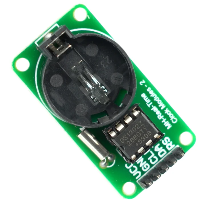
RTC module with the DS1302 chip
A clock that ticks by itself. The little chip marked DS1302Z counts seconds, minutes, hours, days, months and years. Next to it sits a quartz crystal, the same kind of little crystal that keeps time in every wristwatch, and a holder for a coin battery.
What is it for, if the Arduino has millis()? millis() counts the milliseconds since the board was switched on, and it starts from zero at every restart. It does not know what time it is, and when the power is disconnected it forgets everything. The RTC remembers the full date and time, and keeps counting even when the Arduino is switched off.
A fourth way of talking to a module. In the table of interfaces in Part 4 you met UART, SPI and I2C. The DS1302 uses none of them. It has its own three-wire protocol from the company Dallas: CLK (the clock signal that sets the pace), DAT (data in both directions) and RST (the signal “I am talking to you now”). That is why it needs its own library, and why it takes three ordinary digital pins and not SDA/SCL. Those stay free for the display.
| Pin | Function |
|---|---|
VCC | 5 V power |
GND | ground |
CLK | clock signal that sets the pace of the transmission |
DAT | data – the same wire in both directions |
RST | starting and ending the conversation |
⚠️ The coin battery: check this before you start. All the magic of “it remembers the time after it is switched off” sits in a small battery in the holder on the module. It is not in the kit, just like the CR2025 battery for the remote from Part 21. Without it the alarm clock still works, but every time the power is disconnected it forgets the time and you have to set it all over again.
Before you buy a battery, check in the description of your module what type of cell it needs. Modules with the DS1302 are sometimes made at the factory for the rechargeable LIR2032 cell, which the module tops up by itself, and not for the ordinary, single-use CR2032. This is not a small detail: putting an ordinary battery in a place where a charging current flows is not safe. If the description of the module says nothing about it, ask the seller for the information before you put anything into the holder.
03
The 9 V battery clip
A part from the catalog in Part 1 (item 34): the simplest part in the whole kit and the one that changes the character of a project the most.

From the kit
9 V battery clip with a DC plug
No more cable to the computer. On one end a snap for a 9 V battery, on the other a round plug that fits straight into the power socket on the R3 board. No soldering, no breadboard.
The R3 board has a voltage regulator on it: it takes more than 5 V from the DC socket and lowers it by itself to the 5 V that the processor needs. That is why you may feed in 9 V only through this socket, never straight to the 5V pin. There is no protection there any more, and 9 V would destroy the board.
The 9 V battery itself, like the battery for the RTC, is not in the box. It is a part that gets used up, so you buy it separately.
04
The rest of the circuit
Three parts you have known for a long time. Here is just a reminder of what they do in the alarm clock.
From the kit
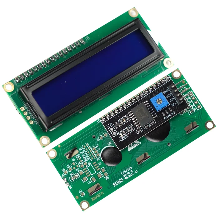
2x16 LCD display
The clock face. The top line shows the date and the time, the bottom line shows the alarm time. It connects through SDA and SCL, the pins on the back of the display. The full explanation is in Part 17.
From the kit
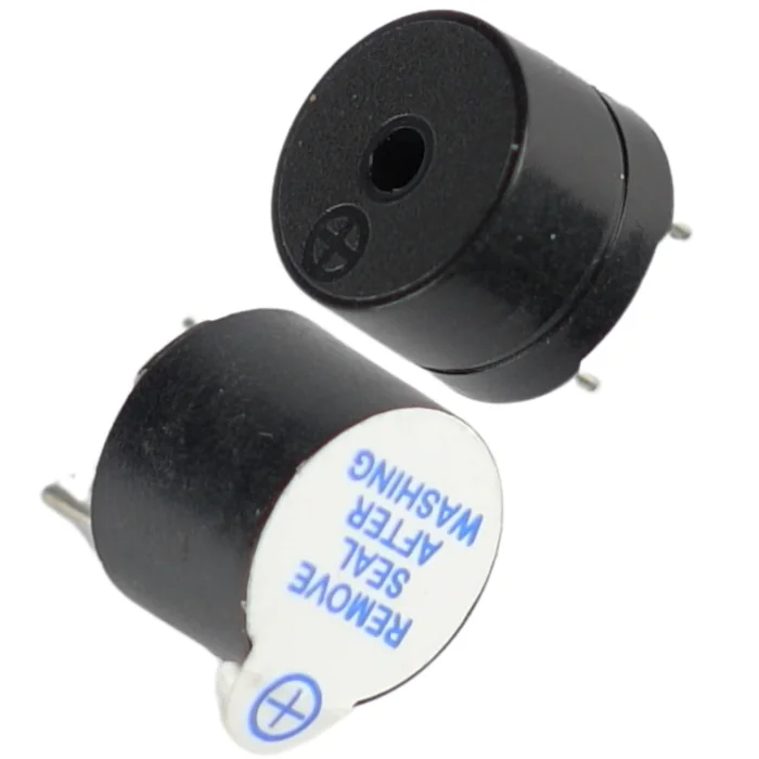
Passive buzzer
The bell. tone() plays in the background, so the buttons work even while the alarm is ringing. The full explanation is in Part 6.
From the kit
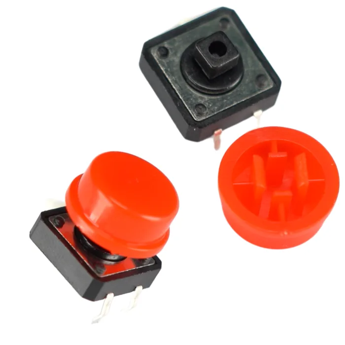
Three tact switch buttons
The control panel. MODE switches what you are setting, + changes the value, STOP turns off the ringing alarm. All with INPUT_PULLUP, without resistors. The full explanation is in Part 5.
05
Building the circuit
Three pins for the clock, three for the buttons, one for the buzzer, and two for the display, which are separate anyway.
What you need: the breadboard, the R3 board, the DS1302 RTC module, the LCD display with the I2C adapter, the passive buzzer, 3 tact switch buttons, about 10 female-to-male jumper wires and a few male-to-male jumper wires. For the part about battery power: the 9 V battery clip and a 9 V battery.
| Part | Pin | Board pin | Note |
|---|---|---|---|
| DS1302 RTC | VCC | “+” rail (5 V) | – |
| DS1302 RTC | GND | “–” rail (GND) | – |
| DS1302 RTC | RST | D2 | – |
| DS1302 RTC | DAT | D3 | – |
| DS1302 RTC | CLK | D4 | – |
| LCD (I2C adapter) | VCC | “+” rail (5 V) | – |
| LCD (I2C adapter) | GND | “–” rail (GND) | – |
| LCD (I2C adapter) | SDA | SDA pin of the R3 board | – |
| LCD (I2C adapter) | SCL | SCL pin of the R3 board | – |
| Passive buzzer | “+” (or the longer leg) | D5 | signal from tone() |
| Passive buzzer | “–” | “–” rail (GND) | – |
MODE button | one leg | D6 | INPUT_PULLUP |
+ button | one leg | D7 | INPUT_PULLUP |
STOP button | one leg | D8 | INPUT_PULLUP |
| All buttons | the leg diagonally opposite | “–” rail (GND) | – |
  RTC DS1302 (its own three-wire protocol):
  D2 --- RST      D3 --- DAT      D4 --- CLK
  VCC from the "+" rail,  GND from the "-" rail

  LCD (I2C adapter, pins on the back of the display):
  SDA --- SDA     SCL --- SCL     VCC from "+",  GND from "-"

  BUZZER:   D5 --| buzzer |-- GND

  BUTTONS (each: one leg to a pin, the leg diagonally opposite to "-"):
  D6 --[ MODE ]-- GND     D7 --[ + ]-- GND     D8 --[ STOP ]-- GND

  POWER FOR THE RAILS:  5V --- "+" rail     GND --- "-" rail
This is the whole circuit on the wiring diagram:
Step-by-step assembly
Build the circuit on the breadboard
Loading the 3D view...
Power the rails of the breadboard
With one jumper wire connect the 5V pin of the R3 board to the “+” rail, with another the GND pin to the “–” rail.
Order of assembly:
- 1Power the rails of the breadboard: one jumper wire from the 5 V pin of the R3 board to the “+” rail, another from the GND pin to the “–” rail.
- 2Connect the RTC module:
VCCto the “+” rail,GNDto the “–” rail,RSTto D2,DATto D3,CLKto D4. - 3Connect the display:
VCCto the “+” rail,GNDto the “–” rail,SDAto the SDA pin,SCLto the SCL pin. - 4Plug in the buzzer: “+” to D5, “–” to the “–” rail.
- 5Plug in the three buttons straddling the groove of the breadboard. One leg of each goes to D6, D7 and D8, the legs diagonally opposite go to the “–” rail.
- 6Check everything once more. Only now plug in the USB cable.
You will connect the 9 V battery at the very end, when the alarm clock is already working. There is a separate passage about it below the program.
06
The program step by step
First you check whether the clock ticks at all. Only then do you build the alarm clock around it.
To work with the DS1302 you need the library Rtc by Makuna. In the editor next to the lesson it has already been added to the project, together with LiquidCrystal_I2C from Part 17. If you ever look for it yourself, type DS1302 into the library search and pick Rtc by Makuna from the list. This library takes care of two traps that the DS1302 catches every beginner in. In a moment you will see which ones.
The clock test: do this first. This program does not use the display or the buttons yet. It only prints the time to the Serial Monitor, so that you can check whether the Arduino gets along with the module at all:
#include <ThreeWire.h>
#include <RtcDS1302.h>

// Order of the arguments: DAT, CLK, RST
ThreeWire rtcWires(3, 4, 2);
RtcDS1302<ThreeWire> rtc(rtcWires);

void setup() {
  Serial.begin(9600);
  rtc.Begin();

  // Trap 1: a fresh DS1302 has its write protection turned on
  if (rtc.GetIsWriteProtected()) {
    rtc.SetIsWriteProtected(false);
  }

  // Trap 2: after a battery is put in, the chip is sometimes stopped
  if (!rtc.GetIsRunning()) {
    rtc.SetIsRunning(true);
  }

  // Type the current date and time here: year, month, day, hour, minute, second
  rtc.SetDateTime(RtcDateTime(2026, 1, 1, 12, 0, 0));
}

void loop() {
  RtcDateTime now = rtc.GetDateTime();

  Serial.print(now.Hour());
  Serial.print(":");
  Serial.print(now.Minute());
  Serial.print(":");
  Serial.println(now.Second());

  delay(1000);
}
Flash the code and open the Serial Monitor (the “Serial Monitor” tab below the editor, speed 9600 baud, as in Part 16). You should see the time going up every second. If the seconds stand still, it is almost certainly one of the two traps, which is why they are in the code from the start:
GetIsWriteProtected()– the DS1302 comes from the factory protected against accidental writing. Until you take the protection off, setting the time simply will not work, and the clock will show some strange values.GetIsRunning()– the chip has a bit that stops the counting of time completely. Fresh from the factory, or after a battery is put in, it is often in exactly that state.
When the time in the Serial Monitor is going up, you can flash the full program of the alarm clock:
#include <Wire.h>
#include <LiquidCrystal_I2C.h>
#include <ThreeWire.h>
#include <RtcDS1302.h>
#include <EEPROM.h>              // permanent memory - as in Part 14

ThreeWire rtcWires(3, 4, 2);             // DAT, CLK, RST
RtcDS1302<ThreeWire> rtc(rtcWires);

LiquidCrystal_I2C lcd(0x27, 16, 2);      // I2C address, columns, rows

const int buzzerPin = 5;
const int modePin   = 6;
const int plusPin   = 7;
const int stopPin   = 8;

// The time at which the alarm clock should ring. These are only starting values -
// on the first start they are overwritten by what was saved in permanent memory.
int  alarmHour   = 7;
int  alarmMinute = 0;
bool alarmOn     = true;

// Three cells of permanent memory in which we keep the alarm settings
const int ADDRESS_HOUR   = 0;
const int ADDRESS_MINUTE = 1;
const int ADDRESS_ON     = 2;

// 0 = clock, 1 = alarm hour, 2 = alarm minute,
// 3 = clock hour, 4 = clock minute, 5 = day, 6 = month
int mode = 0;

bool ringing     = false;
bool alreadyRang = false;
int  previousMinute = -1;
int  previousSecond = -1;

int previousMode = HIGH;
int previousPlus = HIGH;
int previousStop = HIGH;

// ===== HELPER FUNCTIONS =====

// Adds a zero in front, so that the time 7:5 looks like 07:05
String twoDigits(int number) {
  if (number < 10) {
    return "0" + String(number);
  }
  return String(number);
}

// Prints a text and pads it with spaces to 16 characters, so that no leftovers
// of the previous text stay on the screen (just as in Part 23)
void printLine(int row, String text) {
  while (text.length() < 16) {
    text += ' ';
  }
  lcd.setCursor(0, row);
  lcd.print(text);
}

// Returns true only at the moment when the button has just been pressed.
// The & sign lets the function change the variable passed to it.
bool wasPressed(int pin, int &previous) {
  int now = digitalRead(pin);
  bool justPressed = (now == LOW && previous == HIGH);
  previous = now;
  return justPressed;
}

// Changes the clock by the given number of hours or minutes
void changeClock(int byHours, int byMinutes) {
  RtcDateTime t = rtc.GetDateTime();
  int h = (t.Hour() + byHours) % 24;
  int m = (t.Minute() + byMinutes) % 60;
  rtc.SetDateTime(RtcDateTime(t.Year(), t.Month(), t.Day(), h, m, 0));
}

// How many days the given month has. February depends on the leap year: a year is
// a leap year when it divides by 4 but not by 100 - unless it divides by 400.
int daysInMonth(int month, int year) {
  if (month == 2) {
    if ((year % 4 == 0 && year % 100 != 0) || (year % 400 == 0)) {
      return 29;
    }
    return 28;
  }
  if (month == 4 || month == 6 || month == 9 || month == 11) {
    return 30;
  }
  return 31;
}

// Changes the date by the given number of days or months
void changeDate(int byDays, int byMonths) {
  RtcDateTime t = rtc.GetDateTime();

  int year = t.Year();
  int month = t.Month() + byMonths;
  if (month > 12) {
    month = 1;
  }

  int day = t.Day() + byDays;
  int lastDay = daysInMonth(month, year);
  if (day > lastDay) {
    if (byDays > 0) {
      day = 1;         // the days go round in a circle
    } else {
      day = lastDay;   // changing the month must not give April 31
    }
  }

  rtc.SetDateTime(RtcDateTime(year, month, day, t.Hour(), t.Minute(), t.Second()));
}

// Saves the alarm settings to permanent memory. update() instead of write()
// writes a cell only when the value has really changed.
void saveAlarm() {
  EEPROM.update(ADDRESS_HOUR, alarmHour);
  EEPROM.update(ADDRESS_MINUTE, alarmMinute);
  EEPROM.update(ADDRESS_ON, alarmOn);
}

void showScreen(RtcDateTime now) {
  printLine(0, twoDigits(now.Day()) + "." + twoDigits(now.Month()) + "  " +
               twoDigits(now.Hour()) + ":" + twoDigits(now.Minute()) + ":" + twoDigits(now.Second()));

  if (mode == 0) {
    String state = "off";
    if (alarmOn) {
      state = "on";
    }
    printLine(1, "Alarm " + twoDigits(alarmHour) + ":" + twoDigits(alarmMinute) + " " + state);
  } else if (mode == 1) {
    printLine(1, ">Alarm hour: " + twoDigits(alarmHour));
  } else if (mode == 2) {
    printLine(1, ">Alarm min: " + twoDigits(alarmMinute));
  } else if (mode == 3) {
    printLine(1, ">Clock hour: " + twoDigits(now.Hour()));
  } else if (mode == 4) {
    printLine(1, ">Clock min: " + twoDigits(now.Minute()));
  } else if (mode == 5) {
    printLine(1, ">Day: " + twoDigits(now.Day()));
  } else {
    printLine(1, ">Month: " + twoDigits(now.Month()));
  }
}

// ===== SETUP AND LOOP =====

void setup() {
  pinMode(buzzerPin, OUTPUT);
  pinMode(modePin, INPUT_PULLUP);
  pinMode(plusPin, INPUT_PULLUP);
  pinMode(stopPin, INPUT_PULLUP);

  lcd.init();
  lcd.backlight();

  rtc.Begin();

  if (rtc.GetIsWriteProtected()) {
    rtc.SetIsWriteProtected(false);
  }
  if (!rtc.GetIsRunning()) {
    rtc.SetIsRunning(true);
  }

  // We set the time only when the clock does not know it - that is, on the first
  // start or after the battery was changed. This way flashing the program
  // again does not turn the time back.
  if (!rtc.IsDateTimeValid()) {
    rtc.SetDateTime(RtcDateTime(2026, 1, 1, 12, 0, 0));
  }

  // Read the saved alarm. An EEPROM cell that was never written returns 255,
  // so we take the values only when they make sense.
  int hr = EEPROM.read(ADDRESS_HOUR);
  int m = EEPROM.read(ADDRESS_MINUTE);
  if (hr < 24 && m < 60) {
    alarmHour = hr;
    alarmMinute = m;
    alarmOn = EEPROM.read(ADDRESS_ON);
  }
}

void loop() {
  RtcDateTime now = rtc.GetDateTime();
  bool refresh = false;

  // --- BUTTONS ---

  if (wasPressed(modePin, previousMode)) {
    mode = mode + 1;
    if (mode > 6) {
      mode = 0;
    }
    refresh = true;
  }

  if (wasPressed(plusPin, previousPlus)) {
    if (mode == 0) {
      alarmOn = !alarmOn;
    } else if (mode == 1) {
      alarmHour = (alarmHour + 1) % 24;
    } else if (mode == 2) {
      alarmMinute = (alarmMinute + 1) % 60;
    } else if (mode == 3) {
      changeClock(1, 0);
    } else if (mode == 4) {
      changeClock(0, 1);
    } else if (mode == 5) {
      changeDate(1, 0);
    } else {
      changeDate(0, 1);
    }

    saveAlarm();   // thanks to update() nothing is written when the alarm did not change
    refresh = true;
  }

  if (wasPressed(stopPin, previousStop)) {
    ringing = false;
    noTone(buzzerPin);
    mode = 0;
    refresh = true;
  }

  // After a button press: wait out the contact bounce and get the time once more,
  // so that the screen shows the value after the change right away, not the old one
  if (refresh) {
    delay(50);
    now = rtc.GetDateTime();
  }

  // --- ALARM ---

  // Every new minute gives the alarm one chance to ring
  if (now.Minute() != previousMinute) {
    previousMinute = now.Minute();
    alreadyRang = false;
  }

  if (alarmOn && !alreadyRang &&
      now.Hour() == alarmHour && now.Minute() == alarmMinute) {
    ringing = true;
    alreadyRang = true;
  }

  if (ringing) {
    // Half a second of sound, half a second of silence - without stopping the program
    if ((millis() / 500) % 2 == 0) {
      tone(buzzerPin, 1047);
    } else {
      noTone(buzzerPin);
    }
  }

  // --- SCREEN ---

  if (now.Second() != previousSecond) {
    previousSecond = now.Second();
    refresh = true;
  }

  if (refresh) {
    showScreen(now);
  }
}
Write this program in your browser
Tutorial on the left, editor on the right. Build your code and flash it to the board in one click, with nothing to install.
| Instruction | What it does |
|---|---|
ThreeWire rtcWires(3, 4, 2) | describes the three wires of the DS1302 in the order DAT, CLK, RST |
rtc.GetDateTime() | gets the current date and time from the module |
now.Hour(), now.Minute() | pull single values out of it |
rtc.SetDateTime(RtcDateTime(...)) | writes a new time to the module – works only after the write protection is taken off |
rtc.IsDateTimeValid() | tells you whether the clock knows a sensible time; false means the first start or a freshly changed battery |
int &previous | the & sign lets the function change the variable you gave it – this way one function handles all three buttons |
(alarmHour + 1) % 24 | after 23 goes back to 0 – the remainder of a division makes the counting go round in a circle |
daysInMonth(month, year) | makes sure that April 31 cannot be set, and knows the leap year – February then has 29 days |
EEPROM.update(address, value) | saves an alarm setting to permanent memory, but only when it has changed – an EEPROM cell survives about 100,000 writes, and you click + often |
if (hr < 24 && m < 60) | an EEPROM cell that was never written returns 255; without this check a fresh Arduino would show an alarm at 255:255 |
(millis() / 500) % 2 == 0 | cuts time into half-second pieces: an even one – sound, an odd one – silence |
alreadyRang | makes sure the alarm goes off once a minute, and not over and over for the whole 60 seconds |
delay(50) after buttons | waits out the contact bounce – without it one click of + can add two minutes at once |
if (now.Second() != previousSecond) | refreshes the screen only once a second – without it the text would flicker |
This program uses the libraries LiquidCrystal I2C 1.1.2, Rtc by Makuna 2.5.0. They are already added to the project in the editor next to the lesson.
The clock runs, but it shows January 1, 2026. That is how it should be. You will set the time now with the buttons, just like on a real alarm clock. The user manual is in the next section.
Disconnecting the computer
When the alarm clock works and has the time set, do the thing you have been waiting for through twenty-three parts:
- 1Pull the USB cable out of the board. The screen goes dark.
- 2Snap the 9 V battery onto the clip.
- 3Put the round plug of the clip into the power socket of the R3 board. It is the round socket next to the USB connector.
The screen lights up again, and the clock shows the correct time, not January 1. During those dozen or so seconds without power the DS1302 kept counting time on its own coin battery. From this moment the device needs nothing apart from that battery.
07
How to use it
The first project in this series that has its own user manual, because from now on you control it without a computer.
| Button | What it does |
|---|---|
MODE (D6) | goes through the seven modes one after another (see the table below) and returns to the start |
+ (D7) | in clock mode turns the alarm on and off; in the other modes raises the value you are setting by one |
STOP (D8) | silences the ringing alarm and returns to clock mode |
The arrow > on the bottom line shows that you are setting something right now. Without the arrow the screen is in normal mode and shows when the alarm clock will ring.
Presses of MODE | Bottom line | What you set |
|---|---|---|
| 0 | Alarm 07:00 on | nothing – the normal screen, + turns the alarm on and off |
| 1 | >Alarm hour: | the alarm hour |
| 2 | >Alarm min: | the alarm minute |
| 3 | >Clock hour: | the clock hour |
| 4 | >Clock min: | the clock minute |
| 5 | >Day: | the day of the month |
| 6 | >Month: | the month |
Setting the clock after the first power-on: press MODE three times (you will see >Clock hour:), then click + until you see the right hour. Press MODE once more (>Clock min:) and set the minutes the same way. Finish with STOP: you are back on the clock screen. The seconds start from zero at every change of the minutes, so you can get the time right to the second.
Setting the date: press MODE five times (>Day:), click + up to the right day, then press MODE a sixth time (>Month:) and set the month the same way. The program makes sure by itself that the date makes sense: you cannot set April 31, and in a leap year February has 29 days. The year stays the one you typed in the code. The display does not show it anyway.
Setting the alarm: MODE once (>Alarm hour:), set it with +; MODE a second time (>Alarm min:), set it with +; STOP. Make sure the bottom line says on. If it says off, press + in clock mode.
In the morning: the buzzer beeps every half a second until you press STOP. The alarm will ring again the next day at the same time.
Build checklist
Tick them off one by one. Your progress is saved in this browser.
0 / 19
Rules worth remembering
- 1
The 9 V battery is connected only to the round power socket.
Never to the
5Vor3.3Vpin: there is no voltage regulator there, and 9 V will damage the board for good. - 2
Check the type of the coin battery before you put it in.
DS1302 modules are sometimes made for the rechargeable
LIR2032cell, which the module tops up. An ordinaryCR2032in that place is a risk. Check the description of your module. - 3
We rewire the circuit with the power disconnected.
That means with the battery disconnected too, not only with USB unplugged.
- 4
Do not leave the alarm clock with USB and the battery connected at the same time if you do not have to.
The board can cope with both sources, but the battery will run down for no reason. Choose one.
Summary
The alarm clock closes this series not because it is the hardest, but because it is the first one that is finished. It has its own power, its own controls and a memory of time that survives a power cut. That is everything the earlier projects lacked to stop being a demo and start being a device.
On the way you met a fourth way of communicating with a module (after UART, SPI and I2C), you saw why a computer still knows the date after a month in the basement, and you learned to write a program that asks the hardware about its state instead of assuming that everything went well. That is exactly what GetIsWriteProtected() and IsDateTimeValid() do.
And if the alarm clock wakes you up tomorrow morning, it means you have built a thing that works not only when you are looking at it.