XXL Kit for Arduino · Remote control
Part 21 An IR remote and an RGB LED: remote color control
- Beginner
- Ages 8+
- about 60 min
Not a single wire to the Arduino. In this part your project starts taking orders from a remote. The IR receiver will “hear” a button being pressed, and the RGB LED will answer with a color: red, green, blue or a mix of them.
Who is it for? For children and teenagers aged 8 and up, for teachers, and for adults who have done Parts 4 and 16: it helps to know external libraries and digital pins used as outputs.
01
How a remote talks to the Arduino
Zero wires between the remote and the Arduino. This is the first part of the series where control travels through the air, not through a jumper wire.
The remote is not physically connected to anything. When you press a button, the LED inside its case starts flashing very fast, in an exact rhythm. This is infrared light, which the human eye cannot see. The IR receiver in your circuit “sees” these flashes and turns them into an electrical signal, and the Arduino recognizes a particular pattern in it. That pattern means a particular button.
See it with your own eyes. Turn on the camera of a phone and look through it at the LED of the remote while you press any button. Your eye cannot see infrared light, but the phone camera's sensor can. You will see a flickering, purple-white glow, even though to your eye the LED looks completely dark.
The remote of a TV, an air conditioner, a fan or a projector works in exactly the same way. It is one of the oldest and simplest kinds of wireless control, and it is still everywhere because it is cheap and reliable over a short distance.
02
The IR remote
A part from the catalog in Part 1 (item 17). This is the first part where you really use it.
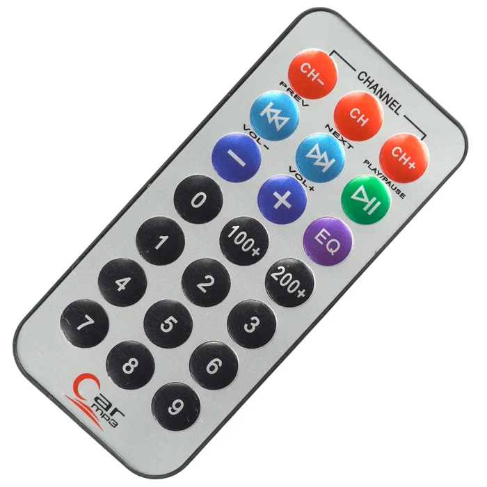
From the kit
IR remote control
A set of buttons, each with its own code. In the kit you will find a small remote with the digit buttons 0–9, the channel arrows CH-/CH/CH+, the volume buttons VOL-/VOL+, PLAY/PAUSE, EQ and 100+/200+. Every button sends a different code of its own.
You don't have to know all the buttons by heart. In the section “The program step by step” you will teach the Arduino to recognize exactly the ones you choose.
Before you start, check the battery. The remote needs a CR2025 coin battery, which you will not find in the kit. Without it the LED in the remote will not blink, and the receiver will receive nothing, even if all the wiring is correct.
03
The IR receiver
A part from the catalog in Part 1 (item 18). It is the “ear” of your project, tuned to infrared light.
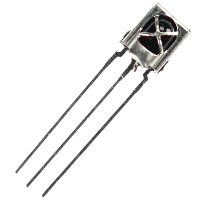
From the kit
IR receiver (infrared)
A filter for one particular kind of light. Inside it has a photodiode that is sensitive to infrared, plus electronics that cut out interference and give a clean, digital pattern of pulses on the output. You could read it with digitalRead(), but in this part a library reads it for you.
The module has three legs: OUT (signal), GND (ground) and VCC (power). Look at the side with the little cross (X) on the case, with the legs pointing towards you. From the left, the order is S (OUT), - (GND), + (VCC).
This is not a part where you may mix up the power, and we don't test it “by feel”. Connecting GND/VCC the wrong way round can draw an unnaturally large current and destroy the module for good, sometimes the very first time you connect it. Don't guess the order of the pins at full power. Instead, make the first connection through a 1 kΩ resistor plugged into the VCC line (between the “+” rail and the leg of the module). It limits the current to a safe level, even if you happen to get the order wrong. Only when the test program from the section “The program step by step” really prints a code after you press a button on the remote do you know the order is right. Then you can leave the resistor in for good (it does not affect the OUT signal) or take it out.
04
The RGB LED
A part from the catalog in Part 1 (item 13). This is the first part where you really light it up.
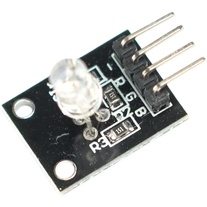
From the kit
RGB LED (module)
Three LEDs in one case. Inside sit a red, a green and a blue LED together, each with its own leg, plus one shared leg. By lighting them in different combinations and at different brightness you can get almost any color. The module from this kit has the pin labels printed on its board: -, R, G, B.
The leg marked - is the common cathode. It goes to “–” (GND), just like the cathode of an ordinary LED. The other three legs (R, G, B) are three independent anodes. Lit one at a time, they give red, green or blue. Lit together, they mix, just as the description in Part 1 promised: “three colors in one case”.
The resistors are already on the board. An ordinary LED always needs its own 220 Ω resistor (the rule from Parts 4–5). But on this module the maker has added them for you: three small SMD parts labeled R1, R2, R3, each printed with 151 (SMD code: 15 × 10¹ = 150 Ω), one on each channel. That is why you connect R, G and B with a jumper wire straight to an Arduino pin, without any extra resistor on the breadboard.
05
The IRremote library
The signal from the remote is a series of pulses whose lengths are counted in microseconds. You could measure them yourself, but somebody has already done it for you.
To work with the receiver you need the IRremote library. Like Keypad in Part 20, it has already been added to the project of this lesson in the editor next to it. It is one of the oldest and most popular libraries in the whole Arduino world: you will find it in almost every project with an IR remote.
The library measures the lengths of the light pulses for you and turns the whole pattern into one simple number: the button's code in the hexadecimal system (HEX), for example 0xF30CBF00. Every button on the remote sends its own, different code.
06
Building the circuit
The receiver listens on one pin, and the RGB LED shines on three. The remote is not connected to anything: it runs on a battery in its own case.
What you need: the breadboard, the R3 board, the IR receiver, the RGB LED module, a 1 kΩ resistor (for testing the receiver), the IR remote, about 8 male-to-male jumper wires. The RGB LED needs no extra resistors: it already has them built in.
An exception to the “nothing extra to buy” rule. The remote needs a CR2025 coin battery. It is not part of the kit, so you have to buy it separately. It is the only thing in this part (and one of very few in the whole series) that you really won't find in the box.
Why D6, D9 and D10, and not D3 or D11? To measure the signal from the receiver, the IRremote library uses a circuit inside the Arduino called Timer2. That is the same circuit analogWrite() uses to make PWM on pins 3 and 11. By sticking to D6, D9 and D10 you avoid a conflict later on. This matters especially in the extended program with brightness control in the section “The program step by step”, where you dim the LED with exactly analogWrite().
| Part | Leg / pin | Goes to | Note |
|---|---|---|---|
| IR receiver | OUT | D2 | signal |
| IR receiver | GND | “–” rail (GND) | – |
| IR receiver | VCC | 1 kΩ resistor → “+” rail (5 V) | protection while you test the order of the pins |
| RGB LED | - | “–” rail (GND) | common cathode |
| RGB LED | R | D6 | resistor already built into the module |
| RGB LED | G | D9 | resistor already built into the module |
| RGB LED | B | D10 | resistor already built into the module |
  IR RECEIVER:
  D2 ── OUT     GND from the "-" rail
                "+" ──[ 1 kΩ ]── VCC   (resistor while you test the pin order)

  RGB LED (common cathode, resistors built into the module):
  D6  ── R  ┐
  D9  ── G  ├── common "-" ── GND
  D10 ── B  ┘
This is the whole circuit on the wiring diagram:
Step-by-step assembly
Build the circuit on the breadboard
Loading the 3D view...
Power the rails of the breadboard
With one jumper wire connect the 5V pin of the R3 board to the “+” rail, with another the GND pin to the “–” rail.
Order of assembly:
- 1Power the rails of the breadboard: a jumper wire from the 5 V pin of the R3 board to the “+” rail, a jumper wire from the GND pin to the “–” rail.
- 2Plug in the IR receiver:
GNDwith a jumper wire to the “–” rail,OUTwith a jumper wire to pin D2. ConnectVCCto the “+” rail through the 1 kΩ resistor: it protects the module while you check the order of the pins. - 3Plug in the RGB LED module:
-with a jumper wire to the “–” rail. - 4With jumper wires connect the LED's pins
R,G,Bstraight to pins D6, D9 and D10, with no resistor on the way. - 5Check everything once more. Only now plug in the USB cable.
07
The program step by step
Every remote has its own codes. First you read them, then you write them into the final program.
Calibration: do this first. Flash this short code to see the codes of your buttons:
#include <IRremote.hpp>

const int receiverPin = 2;

void setup() {
  Serial.begin(9600);
  IrReceiver.begin(receiverPin);
}

void loop() {
  if (IrReceiver.decode()) {
    Serial.println(IrReceiver.decodedIRData.decodedRawData, HEX);
    IrReceiver.resume();
  }
}
Flash the code, open the Serial Monitor (the “Serial Monitor” tab below the editor, speed 9600 baud, as in Part 16) and press, one after another, the four buttons you want to use for red, green, blue and “all at once” (white), for example 1, 2, 3 and 0. Give each button a short press, one press at a time.
In the Serial Monitor you will see only the HEX digits, without the 0x prefix, for example F30CFF00. You add the prefix yourself when you type the code into the program (in C++ the prefix 0x means “this is a hexadecimal number”, but Serial.println(..., HEX) does not print it). Write down the four codes, one for each button.
If you hold a button down for more than a moment, you will see 0 in the Serial Monitor instead of the same code again. That's normal. The remote does not send the whole “package” of data over and over. To keep the air free, it sends a much shorter “repeat” signal, and the IRremote library prints that signal as 0. It is not the code of any button: just ignore it and don't write it down.
One more thing before the final program. Since the “repeat” signal comes out as 0, the final program has to tell it apart from an ordinary code. Otherwise holding a button down would look like pressing a completely different one. The library marks such a signal with a special flag (IRDATA_FLAGS_IS_REPEAT). In the code below we check it and simply ignore the repeats.
I did the same thing you are about to do. When I tested this part, I pressed four chosen buttons on my remote one after another, and the Serial Monitor showed: F30CFF00, E718FF00, A15EFF00, F708FF00. You will get four different numbers, but you type them in exactly the same way. My four lines with CODE_... looked like this:
const unsigned long CODE_RED      = 0xF30CFF00;
const unsigned long CODE_GREEN    = 0xE718FF00;
const unsigned long CODE_BLUE     = 0xA15EFF00;
const unsigned long CODE_WHITE    = 0xF708FF00;
0x is not decoration. It is part of C++ itself and tells the compiler: “read what follows me as a hexadecimal number, not a decimal one”. Without it, E718FF00 in the code would not compile at all: the decimal system has no digits A–F. The test prints just the number, because it is you who decides in the code which system to read it in. That is why you add the prefix.
Once you have the four codes, flash the final program. In place of the four lines CODE_... = 0x0; type your own values from the calibration, with the 0x prefix:
#include <IRremote.hpp>

const int receiverPin = 2;
const int redPin = 6;
const int greenPin = 9;
const int bluePin = 10;

// Fill in your own codes found in the calibration step
const unsigned long CODE_RED      = 0x0;
const unsigned long CODE_GREEN    = 0x0;
const unsigned long CODE_BLUE     = 0x0;
const unsigned long CODE_WHITE    = 0x0;

void setup() {
  pinMode(redPin, OUTPUT);
  pinMode(greenPin, OUTPUT);
  pinMode(bluePin, OUTPUT);
  IrReceiver.begin(receiverPin);
}

void setColor(bool r, bool g, bool b) {
  digitalWrite(redPin, r ? HIGH : LOW);
  digitalWrite(greenPin, g ? HIGH : LOW);
  digitalWrite(bluePin, b ? HIGH : LOW);
}

void loop() {
  if (IrReceiver.decode()) {

    // A button held down sends a short "repeat" frame without the full code -
    // we ignore it instead of mistaking it for some particular button
    if (IrReceiver.decodedIRData.flags & IRDATA_FLAGS_IS_REPEAT) {
      IrReceiver.resume();
      return;
    }

    unsigned long code = IrReceiver.decodedIRData.decodedRawData;

    if (code == CODE_RED)   setColor(true, false, false);
    if (code == CODE_GREEN) setColor(false, true, false);
    if (code == CODE_BLUE)  setColor(false, false, true);
    if (code == CODE_WHITE) setColor(true, true, true);

    IrReceiver.resume();
  }
}
Write this program in your browser
Tutorial on the left, editor on the right. Build your code and flash it to the board in one click, with nothing to install.
| Instruction | What it does |
|---|---|
#include <IRremote.hpp> | from version 4.x on, the library needs the .hpp extension, not .h |
IrReceiver | a ready-made receiver object that the library creates for you – you don't have to declare it |
IrReceiver.begin(receiverPin) | starts listening on the given pin – you call it once, in setup() |
IrReceiver.decode() | returns true when a signal has just been received |
IRDATA_FLAGS_IS_REPEAT | when this flag is set, it is not a new code but the “repeat” sent while you hold a button down – such a frame has no code of its own |
IrReceiver.decodedIRData.decodedRawData | the code of the button that was received – this is what you compare with your CODE_... constants |
IrReceiver.resume() | tells the library “done, keep listening” – without it the next signal will not be received |
setColor(r, g, b) | turns the three channels of the LED on or off at once – the three values true, true, true give white |
This program uses the library IRremote 4.7.1. It is already added to the project in the editor next to the lesson.
Flash the code to the board through FlashESP.com, as in the earlier parts. Press one of your chosen buttons: the LED changes color. Press the one you gave to “white”: all three channels light up at once.
Next step: an off switch and brightness control. Four buttons are only the beginning. The same remote also has VOL-, VOL+ and PLAY/PAUSE, which are great for more than a single color. Go back to the calibration test and read the codes of these three buttons, just as you did for the four colors.
Until now you lit the LED at full power (HIGH) or turned it off (LOW): zero or maximum, nothing in between. The function analogWrite(pin, value) lets you have something in between: a value from 0 (off) to 255 (full brightness), with every step on the way. It works only on PWM pins, and that is exactly why D6, D9 and D10 in this part are PWM pins (see the section “Building the circuit” above).
The extended program:
#include <IRremote.hpp>

const int receiverPin = 2;
const int redPin = 6;
const int greenPin = 9;
const int bluePin = 10;

// Read the codes of the three new buttons and fill in the codes again
const unsigned long CODE_RED      = 0x0;
const unsigned long CODE_GREEN    = 0x0;
const unsigned long CODE_BLUE     = 0x0;
const unsigned long CODE_WHITE    = 0x0;
const unsigned long CODE_OFF      = 0x0;   // e.g. PLAY/PAUSE
const unsigned long CODE_BRIGHTER = 0x0;   // e.g. VOL+
const unsigned long CODE_DIMMER   = 0x0;   // e.g. VOL-

// Which channels should be lit right now
bool activeR = false;
bool activeG = false;
bool activeB = false;

int brightness = 255;             // 0-255
const int BRIGHTNESS_STEP = 25;
bool ledOn = true;

void setup() {
  pinMode(redPin, OUTPUT);
  pinMode(greenPin, OUTPUT);
  pinMode(bluePin, OUTPUT);
  IrReceiver.begin(receiverPin);
}

// One shared point that every change of color, brightness
// or switching off goes through - it works out the final state of the three pins
void refreshLed() {
  if (!ledOn) {
    analogWrite(redPin, 0);
    analogWrite(greenPin, 0);
    analogWrite(bluePin, 0);
    return;
  }

  analogWrite(redPin,   activeR ? brightness : 0);
  analogWrite(greenPin, activeG ? brightness : 0);
  analogWrite(bluePin,  activeB ? brightness : 0);
}

void setColor(bool r, bool g, bool b) {
  activeR = r;
  activeG = g;
  activeB = b;
  ledOn = true;
  refreshLed();
}

void loop() {
  if (IrReceiver.decode()) {

    if (IrReceiver.decodedIRData.flags & IRDATA_FLAGS_IS_REPEAT) {
      IrReceiver.resume();
      return;
    }

    unsigned long code = IrReceiver.decodedIRData.decodedRawData;

    if (code == CODE_RED)        setColor(true, false, false);
    else if (code == CODE_GREEN) setColor(false, true, false);
    else if (code == CODE_BLUE)  setColor(false, false, true);
    else if (code == CODE_WHITE) setColor(true, true, true);
    else if (code == CODE_OFF) {
      ledOn = false;
      refreshLed();
    }
    else if (code == CODE_BRIGHTER) {
      brightness = min(255, brightness + BRIGHTNESS_STEP);
      refreshLed();
    }
    else if (code == CODE_DIMMER) {
      brightness = max(0, brightness - BRIGHTNESS_STEP);
      refreshLed();
    }

    IrReceiver.resume();
  }
}
| Instruction | What it does |
|---|---|
analogWrite(pin, value) | sets the brightness of a channel on a scale of 0–255, instead of only HIGH/LOW |
refreshLed() | one shared point that every change goes through (of color, brightness or switching off); it sets the three pins from the current state |
ledOn | a variable that remembers whether the LED should shine: CODE_OFF switches it off, choosing a color turns it back on |
min(255, brightness + BRIGHTNESS_STEP) | does not let the brightness go above the maximum that analogWrite() accepts |
max(0, brightness - BRIGHTNESS_STEP) | does not let the brightness go below zero |
if / else if | checks the codes in order and stops at the first match: only one action at a time |
Flash it and press VOL+ a few times: the LED gets brighter and brighter, up to the limit of 255. VOL- makes it darker and darker, down to zero. PLAY/PAUSE turns it off completely, whatever the brightness. Choosing a color lights it up again.
Build checklist
Tick them off one by one. Your progress is saved in this browser.
0 / 14
Rules worth remembering
- 1
An LED (any LED, not just an RGB one) always needs a resistor.
On the module from this part the maker has added them for you on the board. But if you ever connect a bare RGB LED without a module, its three legs
R,G,Bwill need three 220 Ω resistors of their own, just like every other LED in this series. - 2
An RGB LED has polarity.
The
-leg is the common cathode. It always goes to “–” (GND), whichever channel you are lighting. - 3
We rewire the circuit with the power disconnected.
Pull out the USB, move the wires, check once more and only then plug it back in.
- 4
You check the pin order of the IR receiver through a 1 kΩ resistor on
VCC, not “by feel”.If
GNDandVCCswap places, the power to the module is reversed, and that can damage it for good. An LED is different: with the wrong polarity it simply does not shine. The resistor limits the current during the test, so a mistake in the order ends safely, not with heat. If something gets hot even with the resistor, unplug the USB at once.
Projects
None of the projects below needs anything extra: everything is already in the kit. They go roughly from the easiest to the most ambitious.
- 1
A two-color signal
Easy- What you will use
- the remote + the RGB LED (2 buttons)
- What you will learn
- comparing a HEX code with a simple
if
- 2
A color carousel
Easy- What you will use
- the remote + the RGB LED (1 button)
- What you will learn
- using a counter variable that moves on to the next color on the list with every press
- 3
Smooth changes between colors
Medium- What you will use
- the remote + the RGB LED
- What you will learn
- using
analogWrite()andmillis()to make one color slowly “melt” into another
- 4
A remembered color and brightness
Challenging- What you will use
- the remote + the RGB LED + EEPROM from Part 14
- What you will learn
- saving the last state in permanent memory, so that it survives a restart of the board
- 5
One remote, two devices
Challenging- What you will use
- the remote + the RGB LED + the relay from Part 16
- What you will learn
- sharing out the codes from one remote among several independent outputs
Summary
This part joined wireless control with color. The remote from Part 1 finally sent its first signal, the IR receiver “heard” it, and the IRremote library turned the pulses of light into simple HEX codes. The RGB LED answered these codes with color: for the first time in this series, one actuator showed more than “on” or “off”. The codes you read yourself during calibration will work only with your own remote, and that's fine: that is simply how infrared works.