XXL Kit for Arduino · Lighting
Part 19 A photoresistor and a sound sensor: smart lighting
- Beginner
- Ages 8+
- about 60 min
Two completely different signals, one effect: a light switched on. The photoresistor will detect dusk, the sound sensor will detect a clap, and the relay from Part 16 will at last do what it is really for: it will physically switch on a separate circuit with an LED, instead of only “clicking” with nothing connected.
Who is it for? For children and teenagers aged 8 and up, for teachers, and for adults who have done Parts 5 and 16: it helps to know the voltage divider and the relay.
01
How smart lighting works
Two completely different signals, but the same result. This is the first part where two independent conditions turn on one output.
| Situation | What happens | How long |
|---|---|---|
| It got dark | the light turns on and stays on | as long as it is dark |
| A clap (during the day) | the light turns on for a moment | 5 seconds, then it goes out by itself |
| Bright and quiet | the light is off | – |
It is exactly the same idea as in real “clappers”, the plug-in gadgets that your grandparents already knew: a clap turns on a lamp, and dusk can do the same without any clapping. In your circuit both signals, independently of each other, control one and the same relay.
02
The GL5528 photoresistor
A part from the catalog in Part 1 (item 23): the same voltage divider trick as with the potentiometer and the flame sensor.
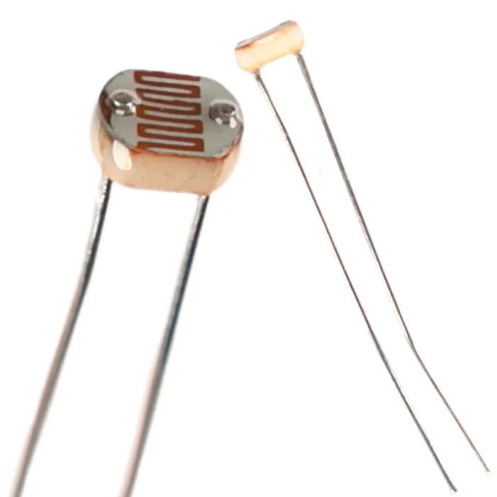
From the kit
GL5528 photoresistor (LDR)
More light, less resistance. The zigzag track on its surface is a semiconductor whose electrical resistance falls when more light lands on it.
The photoresistor has no polarity: you can plug it in either way round. You connect it like the potentiometer in Part 5 and the photodiode in Part 18: as a voltage divider. This time the photoresistor is on the “+” side and the 10 kΩ resistor on the “–” side. In this order more light raises the reading on the analog pin instead of lowering it, as it did with the flame sensor.
03
The sound sensor (“clap sensor”)
A part from the catalog in Part 1 (item 26): a ready-made sensitivity threshold, with nothing to calculate in the code.
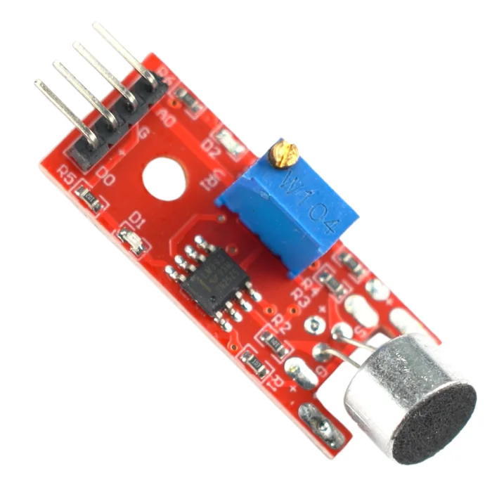
From the kit
Sound sensor module (microphone + comparator)
It does not hear words, only loudness. The microphone turns sound into a voltage, and the circuit on the board compares it with a threshold. When the sound is loud enough, the D0 output jumps to HIGH for a moment.
The module has four pins: A0 (the raw analog signal, not used in this project), G (ground), + (power) and D0 (the ready-made digital signal: this is the one you want). The blue potentiometer on the board sets the sensitivity: you turn it with a screwdriver instead of tuning a threshold in the code. That is exactly the opposite of the flame sensor in Part 18, where you did the calibration in the program.
04
The relay: COM, NO and NC
A part from Part 16, where it only “clicked” with nothing connected. Now you will finally connect something to its screw terminal.
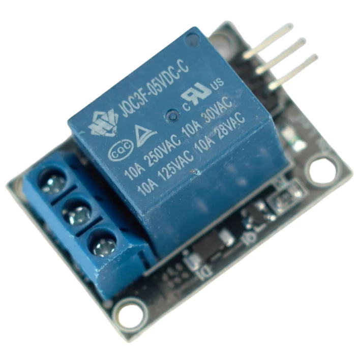
From the kit
5 V relay module
An electric switch controlled from the Arduino. On one side it has three pins for the R3 board, on the other a screw terminal with three contacts. That is where you will plug in the circuit to be switched. The full explanation of how it works is in Part 16.
Reminder from Part 16: the relay has a control side (VCC, GND, IN, which you connect to the R3 board) and a switched side (three screws). The three screws are:
| Contact | What it means | When it is connected to COM |
|---|---|---|
COM | the common contact – the “middle” of the switch | always physically connected to one of the two below |
NO (Normally Open) | “normally open” | only when the relay is switched on |
NC (Normally Closed) | “normally closed” | as long as the relay is switched off |
In other words: with no signal on IN, the circuit COM–NC is closed and COM–NO is open. When the Arduino switches the relay on, the electromagnet moves the contact: COM–NO closes and COM–NC opens. In this project you use the pair COM–NO: the circuit with the LED should be closed (the LED shines) only when the relay is switched on.
The exact layout of the labels next to the screws differs from one module maker to another. Check the tiny print beside each screw on your own module before you connect the wires.
05
Reminder: the LED and the resistor
No new hardware apart from the sensors. The rest are parts you already know from Parts 4 and 5.
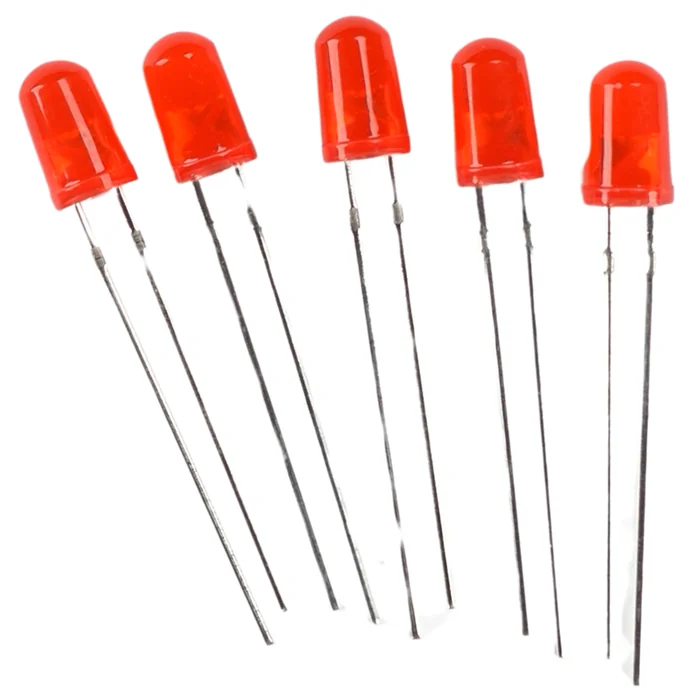
From the kit
LED (red) – stands in for the light
The anode (the longer leg) always goes through a resistor. The full explanation of polarity is in Parts 4 and 5.
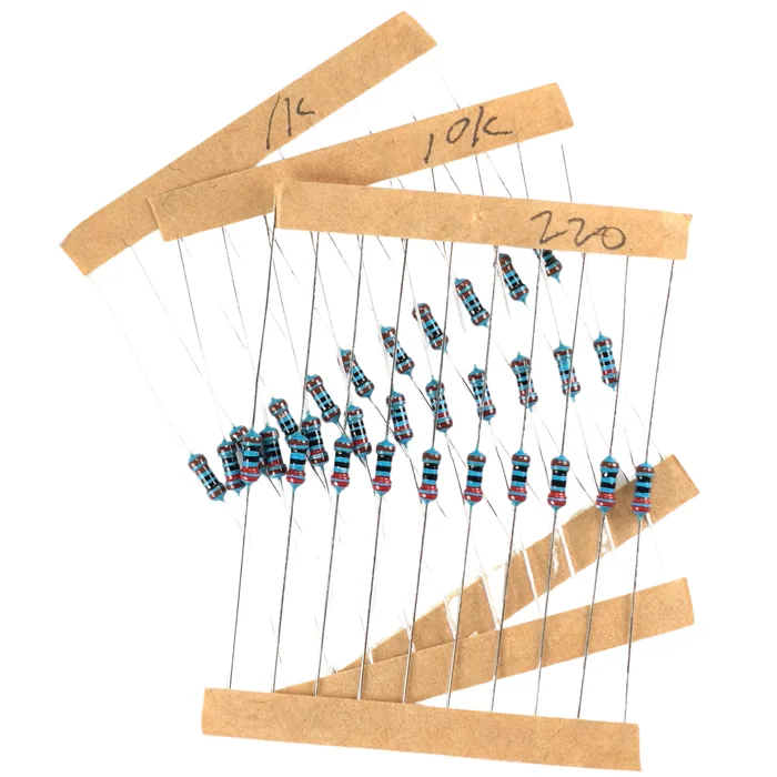
From the kit
220 Ω and 10 kΩ resistors
220 Ω for the LED, 10 kΩ as the lower arm of the photoresistor's voltage divider. You will find both in the set of resistors.
06
Building the circuit
Two independent input sensors and one output circuit that is switched physically, not in the program.
What you need: the breadboard, the R3 board, the GL5528 photoresistor, the sound sensor module, the relay module, a 10 kΩ resistor, a 220 Ω resistor, an LED (red), about 11 male-to-male jumper wires.
| Part | Leg / pin | Goes to | Note |
|---|---|---|---|
| Photoresistor | one leg | 5 V | no polarity |
| Photoresistor | other leg | the row with the 10 kΩ resistor and pin A0 | a shared row – this is the voltage divider |
| 10 kΩ resistor | one end | the row with the photoresistor and pin A0 | – |
| 10 kΩ resistor | other end | “–” rail (GND) | – |
| Sound sensor | + | 5 V | – |
| Sound sensor | G | “–” rail (GND) | – |
| Sound sensor | D0 | D2 | ready-made digital signal |
| Relay | VCC | 5 V | – |
| Relay | GND | “–” rail (GND) | – |
| Relay | IN | D8 | the signal that switches it on |
| Relay | COM (screw terminal) | “+” rail (5 V) | – |
| Relay | NO (screw terminal) | 220 Ω resistor → the LED's anode | closes only when the relay is switched on |
| Red LED | cathode (shorter leg) | “–” rail (GND) | – |
  PHOTORESISTOR (voltage divider):
  5V ──[ photoresistor ]──┬── A0
                          │
                       [ 10 kΩ ]
                          │
                         GND

  SOUND SENSOR (ready-made digital signal):
  D2 ── sensor D0         "+" from the "+" rail, "G" from the "-" rail

  RELAY - CONTROL SIDE:
  D8 ── relay IN          VCC and GND from the breadboard rails

  RELAY - SWITCHED SIDE (screw terminal):
  "+" ── COM   NO ──[ 220 Ω ]──►|── GND
This is the whole circuit on the wiring diagram:
Step-by-step assembly
Build the circuit on the breadboard
Loading the 3D view...
Power the rails of the breadboard
With one jumper wire connect the 5V pin of the R3 board to the “+” rail, with another the GND pin to the “–” rail.
Order of assembly:
- 1Power the rails of the breadboard: a jumper wire from the 5 V pin of the R3 board to the “+” rail, a jumper wire from the GND pin to the “–” rail.
- 2Plug in the photoresistor: one leg to the “+” rail, the other into a free row. Plug the 10 kΩ resistor into the same row, with its other end to the “–” rail. With a jumper wire connect the photoresistor's row to pin A0.
- 3Plug in the sound sensor module:
+to the “+” rail,Gto the “–” rail,D0to pin D2. - 4Plug in the relay module:
VCCto the “+” rail,GNDto the “–” rail,INto pin D8. - 5Connect wires to the screw terminal of the relay:
COMto the “+” rail,NOto one end of the 220 Ω resistor. - 6Connect the other end of the 220 Ω resistor to the LED's anode, and the LED's cathode with a jumper wire to the “–” rail.
- 7Check everything once more. Only now plug in the USB cable.
07
The program step by step
Two independent conditions, one output. Darkness wins and keeps the light on all the time.
Calibration – do this first. You will almost certainly have to tune both sensors to your room before the final program works as it should. Flash this short code:
const int photoresistorPin = A0;
const int clapSensorPin = 2;

void setup() {
  Serial.begin(9600);
  pinMode(clapSensorPin, INPUT);
}

void loop() {
  Serial.print("Photoresistor: ");
  Serial.print(analogRead(photoresistorPin));

  if (digitalRead(clapSensorPin) == HIGH) {
    Serial.println("   <- CLAP!");
  } else {
    Serial.println();
  }

  delay(25);
}
Check the result in the Serial Monitor (the “Serial Monitor” tab below the editor, speed 9600 baud, as in Part 16). It is important that the loop checks the sound sensor often and without long delays. A clap is very short, and checking too rarely (for example once every few hundred milliseconds) can miss it completely, even though the sensor worked correctly. The delay(25) in this code is a safe compromise. The final program below has no such delay at all, so this problem does not affect it.
The photoresistor: write down the reading in normal light and the reading with your hand covering it, and set darknessThreshold in the code below somewhere between them. The sound sensor: watching for the text “CLAP!” in the Serial Monitor, turn the blue potentiometer on the module with a small screwdriver until ordinary silence and background noise no longer trigger it, but a real clap still does. The direction to turn differs from one module to another, so simply watch which way things get better.
When you have good values, flash the final program:
const int photoresistorPin = A0;
const int clapSensorPin = 2;
const int relayPin = 8;

const int darknessThreshold = 400;   // tune it with the method from the calibration section above

void setup() {
  pinMode(clapSensorPin, INPUT);
  pinMode(relayPin, OUTPUT);
}

void loop() {
  int brightness = analogRead(photoresistorPin);

  if (brightness < darknessThreshold) {
    digitalWrite(relayPin, HIGH);   // dark - the light stays on all the time
    return;                         // skip checking for a clap
  }

  if (digitalRead(clapSensorPin) == HIGH) {
    digitalWrite(relayPin, HIGH);   // a clap - the light on for a moment
    delay(5000);
  }

  digitalWrite(relayPin, LOW);
}
Write this program in your browser
Tutorial on the left, editor on the right. Build your code and flash it to the board in one click, with nothing to install.
| Instruction | What it does |
|---|---|
analogRead(photoresistorPin) | reads the brightness as a number 0–1023 – more light, higher value |
if (brightness < darknessThreshold) | checked first – darkness takes priority over a clap |
return | ends this turn of loop() right away, so the rest of the code (checking for a clap) does not run at all |
digitalRead(clapSensorPin) | reads the ready-made D0 signal from the module – HIGH when the sound is loud enough |
delay(5000) | keeps the light on for 5 seconds after a clap, before the code moves on to switching it off |
Flash the code to the board through FlashESP.com, as in the earlier parts. During the day, clap loudly close to the microphone: the LED lights up for 5 seconds and goes out. Cover the photoresistor with your hand to simulate dusk: the LED lights up and stays on as long as you keep it covered.
Build checklist
Tick them off one by one. Your progress is saved in this browser.
0 / 13
Rules worth remembering
- 1
Connect only low voltage from the same board (5 V) to the screw terminal of the relay.
Never 230 V mains voltage. This rule holds for the whole series, with no exceptions.
- 2
An LED always needs a 220 Ω resistor, and it has polarity.
The longer leg (the anode) to the resistor, the shorter one (the cathode) to “–”.
- 3
We rewire the circuit with the power disconnected.
Pull out the USB cable, move the jumper wires, check once more and only then plug it back in.
Projects
None of the projects below needs anything extra: everything is already in the kit. They go roughly from the easiest to the most ambitious.
- 1
A night light without clapping
Easy- What you will use
- the photoresistor + the relay (without the sound sensor)
- What you will learn
- simplifying a circuit to one input
- 2
A clapper without dusk
Easy- What you will use
- the sound sensor + the relay (without the photoresistor)
- What you will learn
- working with a ready-made digital signal from a module
- 3
A double clap turns it on, a single clap does nothing
Medium- What you will use
- the sound sensor
- What you will learn
- measuring the time between events with the
millis()function
- 4
Gradual dimming instead of a switch
Medium- What you will use
- the photoresistor + an LED (without the relay)
- What you will learn
- replacing a threshold with smooth control through
analogWrite()
- 5
A light direction detector
Medium- What you will use
- 2 photoresistors + two 10 kΩ resistors
- What you will learn
- comparing two independent sensors to find out which side is brighter
- 6
Automatic lighting that remembers its last state
Challenging- What you will use
- both sensors + EEPROM from Part 14
- What you will learn
- saving a state in permanent memory so that it survives a restart
Summary
This part joined two independent inputs to one output. For the first time in this series two completely different conditions (a brightness threshold and a digital signal from a module) controlled the same effect. Above all, though, the relay from Part 16 finally stopped just “clicking” with nothing connected: you met COM, NO and NC and used them to physically switch a separate circuit. The same COM/NO pair will come back later in the series, when the relay again has something real to switch.