XXL Kit for Arduino · Safety
Part 18 Water level and flame sensors: a fire safety system
- Beginner
- Ages 8+
- about 60 min
Two completely different dangers, and one small system that watches for both. The water level sensor will detect a flood, the flame sensor will detect fire, and the Arduino will decide which one matters more if both go off at once. This is the first part of the series in which the program has to choose a priority between two dangers by itself.
Who is it for? For children and teenagers aged 8 and up, but only under adult supervision: you test this part with an open flame. For adults, it helps to know the analog input and the voltage divider from Part 5.
01
How the safety system works
Two independent sensors, one decision: what to signal when the dangers overlap.
| State | LED | Buzzer | What triggers it |
|---|---|---|---|
| Safe | off | silent | both readings normal |
| Flood | blinks slowly | a single beep every little while | the water level went over the threshold |
| Fire | blinks fast | a continuous, loud alarm | the flame sensor detected fire |
If both dangers happened at once, the system always reports fire. Real alarm systems follow the same rule: fire usually needs a faster reaction than a flood, so it gets priority in the code.
02
The water level sensor
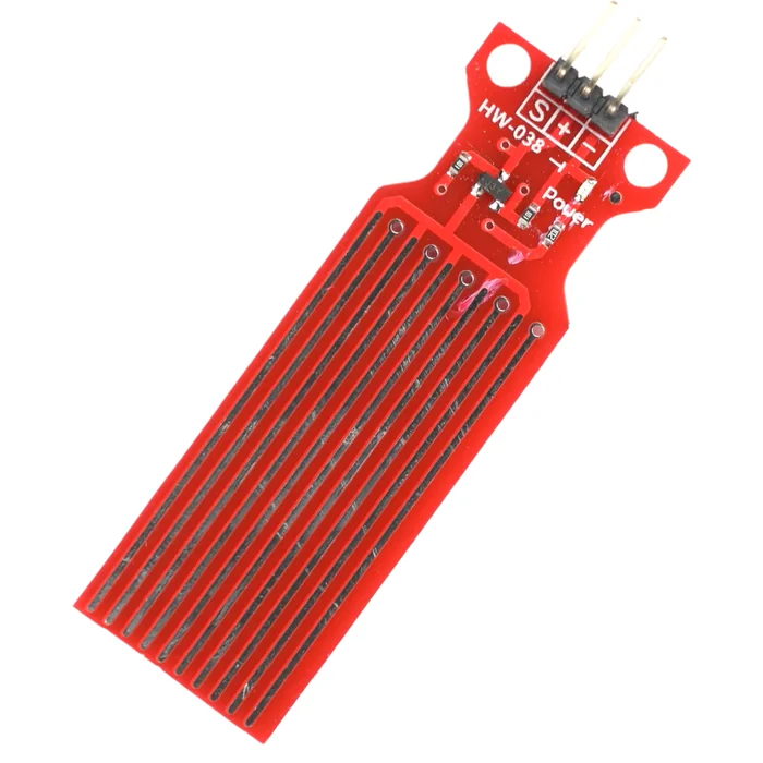
A part from the catalog in Part 1 (item 24): a ready-made module, with no resistors to work out.
From the kit
Analog water level sensor (HW-038)
More water, higher reading. A comb of parallel tracks on the board. The higher the water reaches, the more of them it joins together, and the higher the voltage on the S output.
The module has three marked legs: S (the analog signal), + and -. All the electronics that calibrate the reading already sit on the board. You connect three wires and right away you have a number 0–1023 that grows with the water level.
03
The flame sensor
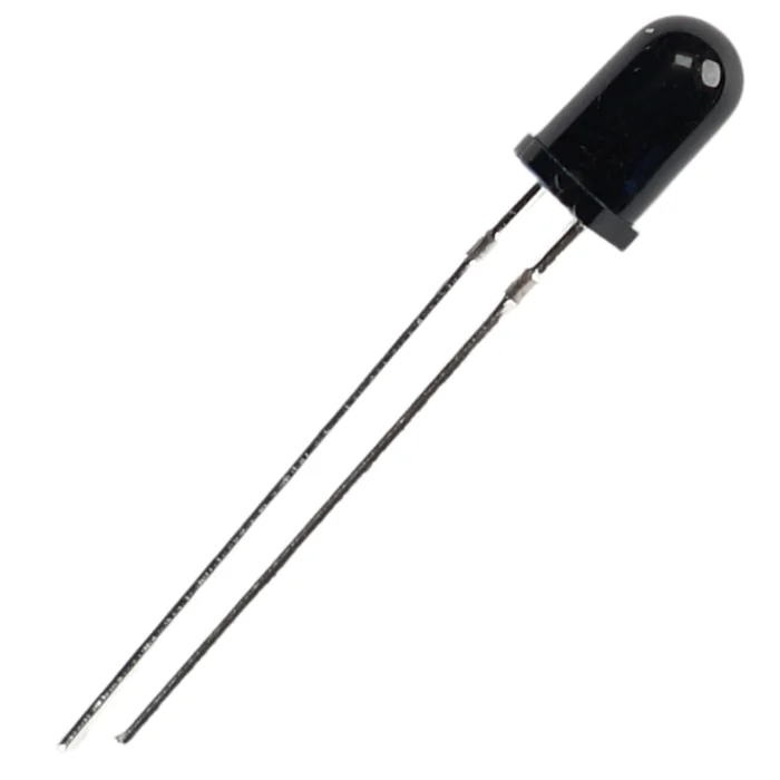
A part from the catalog in Part 1 (item 25): just two bare legs. This time you build the voltage divider yourself.
From the kit
Flame sensor
A phototransistor that is sensitive to infrared. A flame shines strongly in infrared, which your eye cannot see. That is exactly the kind of light this part reacts to.
Is it really a “flame sensor”? The phototransistor itself does not know that it is looking at fire. It simply reacts to light in the near-infrared range, where a flame shines exceptionally strongly, much more strongly than ordinary room lighting. Thanks to that, in practice it detects a flame well from a short distance, and that is why it is sold and named exactly this way, also in the catalog in Part 1. Still, it is not a chemical sensor or a heat sensor. It is an ordinary light detector tuned to one range: strong sunlight, an incandescent bulb or an IR remote can set it off too. A false alarm from bright light is not a fault. It is simply a property of this type of sensor, and worth remembering when you calibrate the threshold below.
Unlike the water level sensor, this part is a bare phototransistor: two legs and no board with electronics. You connect it the way you connected the potentiometer in Part 5: as a voltage divider. One leg goes to “+” through a 10 kΩ resistor. It is the same idea as the “pull-up resistor” of the button in Part 5, only there it was built into the R3 board and you turned it on with INPUT_PULLUP alone, without any physical part. The phototransistor has no built-in help, so this time you really plug the resistor in yourself, on the breadboard. The other leg of the phototransistor goes to “–”. You connect the point between the resistor and the phototransistor to an analog pin. The more infrared falls on the sensor, the better it conducts and the lower the voltage you will see on the analog input. That is the opposite of the photoresistor (a different part, which you will meet in Part 19), where more light usually raises the reading.
Why 10 kΩ exactly? The voltage at the output of the divider does not depend on the value of the resistor alone, but on the ratio between it and the resistance of the phototransistor, and that one changes with the amount of light falling on it. The divider is most sensitive when the two resistances are roughly the same size. A resistor that is too small (for example 1 kΩ) dominates the divider. The voltage on A1 stays “trapped” near the upper limit almost whatever the light, because to really pull it down the resistance of the phototransistor would have to drop below that small value, and it does not go that low. A resistor that is too big works the other way: the divider saturates even in weak light and can no longer tell the difference. 10 kΩ hits a sensible middle for this part: in good light the reading can fall from ~1023 to just a few dozen, so you have a wide, clear range for setting the threshold fireThreshold in the code below.
The case has no polarity marking. If the sensor does not react to light after assembly, simply swap its two legs.
04
Reminder: the LED and the buzzer
No new hardware apart from the sensors. The rest are parts you already know from Parts 4–6.
From the kit
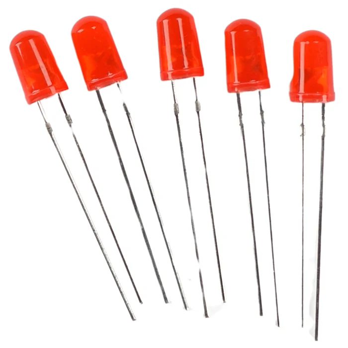
LED (red) – the signal
The anode (the longer leg) always goes through a resistor. The full explanation of polarity is in Parts 4 and 5.
From the kit
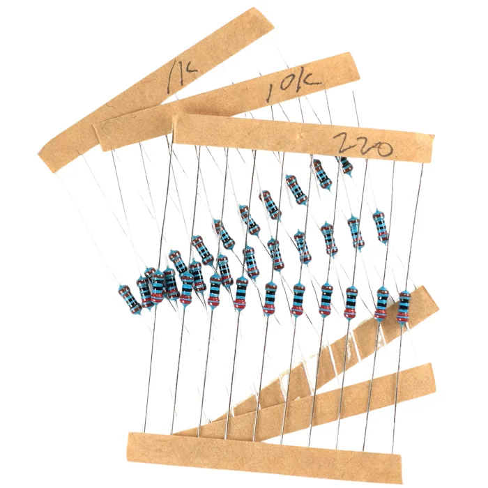
220 Ω and 10 kΩ resistors
220 Ω for the LED, 10 kΩ as the pull-up resistor of the flame sensor. You will find both in the set of resistors.
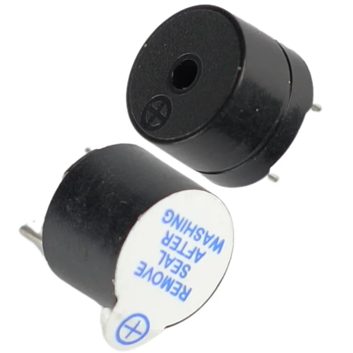
From the kit
Passive buzzer – the alarm
Controlled with the tone() function. The full explanation is in Part 6.
05
Building the circuit
One ready-made module and one voltage divider built from scratch: two different approaches to the same kind of reading.
What you need: the breadboard, the R3 board, the water level sensor, the flame sensor, a 10 kΩ resistor, a 220 Ω resistor, an LED (red), the passive buzzer, about 9 male-to-male jumper wires.
| Part | Leg / pin | Goes to | Note |
|---|---|---|---|
| Water level sensor | S | A0 | analog input |
| Water level sensor | + | 5 V | – |
| Water level sensor | - | “–” rail (GND) | – |
| 10 kΩ resistor | one end | 5 V | – |
| 10 kΩ resistor | other end | leg 1 of the flame sensor and pin A1 | a shared row – this is the voltage divider |
| Flame sensor | leg 1 | the row with the 10 kΩ resistor and pin A1 | – |
| Flame sensor | leg 2 | “–” rail (GND) | swap the legs if it does not react |
| 220 Ω resistor | one end | pin 9 | – |
| 220 Ω resistor | other end | the LED's anode | – |
| Red LED | cathode (shorter leg) | “–” rail (GND) | – |
| Passive buzzer | “+” | pin 8 | – |
| Passive buzzer | “–” | “–” rail (GND) | – |
  WATER LEVEL SENSOR (ready-made module):
  A0 ── sensor S           "+" from the "+" rail, "-" from the "-" rail

  FLAME SENSOR (a voltage divider you build yourself):
  5V ──[ 10 kΩ ]──┬── A1
                  │
               phototransistor
                  │
                 GND

  LED (through 220 Ω):
  9 ──[ 220 Ω ]──►|── GND

  BUZZER:
  8 ── buzzer ── GND
This is the whole circuit on the wiring diagram:
Step-by-step assembly
Build the circuit on the breadboard
Loading the 3D view...
Power the rails of the breadboard
With one jumper wire connect the 5V pin of the R3 board to the “+” rail, with another the GND pin to the “–” rail.
Order of assembly:
- 1Power the rails of the breadboard: a jumper wire from the 5 V pin of the R3 board to the “+” rail, a jumper wire from the GND pin to the “–” rail.
- 2Plug in the water level sensor and connect it:
+to the “+” rail,-to the “–” rail,Sto pin A0. - 3Plug in the phototransistor of the flame sensor. Connect one leg with a jumper wire to pin A1, and join to it one end of the 10 kΩ resistor, whose other end goes to the “+” rail. Connect the other leg of the phototransistor with a jumper wire to the “–” rail.
- 4Plug in the 220 Ω resistor between pin 9 and a free row, plug the LED's anode into the same row, and connect the cathode with a jumper wire to the “–” rail.
- 5Plug in the buzzer: “+” to pin 8, “–” to the “–” rail.
- 6Check everything once more. Only now plug in the USB cable.
06
The program step by step
Before the state machine works well, both thresholds have to be tuned to your conditions. See “Calibration” below the code.
const int waterLevelPin = A0;
const int flamePin = A1;
const int ledPin = 9;
const int buzzerPin = 8;

const int waterThreshold = 300;   // tune after calibration - see the description below the code
const int fireThreshold = 500;    // tune after calibration - see the description below the code

const int SAFE = 0;
const int FLOOD = 1;
const int FIRE = 2;

void setup() {
  pinMode(ledPin, OUTPUT);
  pinMode(buzzerPin, OUTPUT);
}

void loop() {
  int waterReading = analogRead(waterLevelPin);
  int fireReading = analogRead(flamePin);

  int state = SAFE;
  if (fireReading < fireThreshold) {
    state = FIRE;              // fire has priority over a flood
  } else if (waterReading > waterThreshold) {
    state = FLOOD;
  }

  switch (state) {
    case SAFE:
      digitalWrite(ledPin, LOW);
      noTone(buzzerPin);
      break;

    case FLOOD:
      digitalWrite(ledPin, HIGH);
      tone(buzzerPin, 800);
      delay(200);
      noTone(buzzerPin);
      digitalWrite(ledPin, LOW);
      delay(800);
      break;

    case FIRE:
      digitalWrite(ledPin, HIGH);
      tone(buzzerPin, 1500);
      delay(100);
      digitalWrite(ledPin, LOW);
      delay(100);
      break;
  }
}
Write this program in your browser
Tutorial on the left, editor on the right. Build your code and flash it to the board in one click, with nothing to install.
| Instruction | What it does |
|---|---|
analogRead(waterLevelPin) | reads the water level as a number 0–1023 – more water, higher value |
analogRead(flamePin) | reads the voltage divider of the flame sensor – more infrared, lower value |
if (fireReading < fireThreshold) is checked first | makes sure that a fire is never hidden by the flood alarm |
switch (state) | three branches instead of nested ifs – the same mechanism as in Part 15 |
tone(buzzerPin, 800) / tone(buzzerPin, 1500) | different pitches and blinking rhythms tell a flood from a fire by ear and by eye |
Flash the code to the board through FlashESP.com, as in the earlier parts.
Calibration. The values of waterThreshold and fireThreshold in this code are only a starting point. Yours will be different, because they depend on the particular sensor, the water and the lighting in your room. Before you decide that something does not work, flash for a moment a version with Serial.begin(9600) in setup() and a Serial.print() of both readings in loop(), and check the result in the Serial Monitor (the “Serial Monitor” tab below the editor, speed 9600 baud, exactly as in Part 16). Write down the reading when everything is calm, and then – under adult supervision – the reading with a real danger (see “Rules worth remembering” below), and set the thresholds somewhere between those two values.
Build checklist
Tick them off one by one. Your progress is saved in this browser.
0 / 12
Rules worth remembering
- 1
Test the flame sensor only with an open flame and only under adult supervision.
Hold the flame (for example a lighter or a match) at least 15–20 cm away from the sensor and from the rest of the circuit, never directly over the wires or the breadboard. Put the flame out as soon as the test is over.
- 2
Dip the water level sensor in only up to the line marked “Power”.
The electronics above that line are not waterproof. Only the comb of tracks itself should be in the water.
- 3
An LED always needs a 220 Ω resistor, and it has polarity.
The longer leg (the anode) to the resistor, the shorter one (the cathode) to “–”.
- 4
We rewire the circuit with the power disconnected.
Pull out the USB cable, move the jumper wires, check once more and only then plug it back in.
Projects
None of the projects below needs anything extra: everything is already in the kit. They go roughly from the easiest to the most ambitious.
- 1
A silent flood detector
Easy- What you will use
- the water level sensor + an LED
- What you will learn
- using a simple threshold on one analog input
- 2
A fire alarm with a continuous sound
Easy- What you will use
- the flame sensor + the buzzer
- What you will learn
- building a voltage divider from a bare part
- 3
Two independent alarms
Medium- What you will use
- 2 LEDs (without a shared priority)
- What you will learn
- signaling both dangers at once, without choosing one
- 4
Automatic calibration at startup
Medium- What you will use
- both sensors
- What you will learn
- reading the “calm state” in
setup()and calculating a relative threshold instead of a fixed one
- 5
An alarm logger
Challenging- What you will use
- both sensors + EEPROM from Part 14
- What you will learn
- saving in permanent memory how many times an alarm went off and for which danger
Summary
This part brought together two completely different ways of working with an analog sensor: a ready-made module that you only have to connect (the water level sensor), and a bare part from which you build the voltage divider yourself (the flame sensor), with exactly the same technique as for the potentiometer in Part 5. The logic itself was new too: for the first time in this series the program had to decide which of two independent dangers to report as the more important one when both overlap.