XXL Kit for Arduino · Temperature
Part 17 Temperature and humidity: LM35DZ, DHT11 and an LCD
- Beginner
- Ages 8+
- about 60 min
Two sensors measure the same thing, temperature, but in completely different ways: the LM35DZ gives a raw voltage that you convert to degrees yourself, and the DHT11 gives a ready number (and the humidity of the air along the way). In this part you will build a mini weather station, compare the two approaches live and show the result on an LCD screen.
Who is it for? For children and teenagers aged 8 and up, for teachers, and for adults who have done Part 16: it helps to know external libraries.
01
Analog versus digital
Two ways to measure the same thing: one raw and fast, the other ready-made but slower.
The LM35DZ is an analog sensor. On its output there is a voltage that rises and falls smoothly with the temperature. The Arduino can read this voltage at any moment with analogRead(), but by itself it is only a number from 0 to 1023. You are the one who converts it to degrees Celsius in the code.
The DHT11 is a digital sensor. Inside it has its own tiny chip, which has already measured the temperature and the humidity and sends the Arduino a ready, rounded number, using a special protocol over one wire. You do not have to convert anything, but in return you cannot ask it non-stop. It needs a break of about a second between readings, and sometimes a reading fails and you have to try again.
Neither way is “better”. It is a trade-off you will meet very often in electronics: a raw and instant signal versus a ready but slower result.
02
The LM35DZ temperature sensor
A part from the catalog in Part 1 (item 21). There you only saw its picture. Now you finally get to connect it.
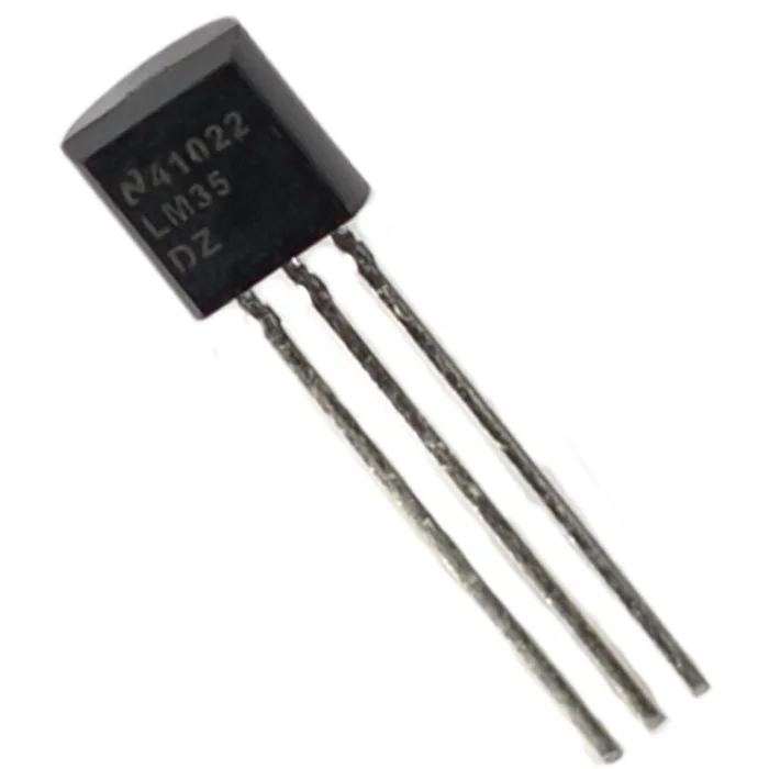
From the kit
LM35DZ temperature sensor
A voltage that rises with the temperature. It looks like a small transistor in a black case, but inside it has a circuit that puts out 10 millivolts for every degree Celsius.
The LM35DZ has three legs, arranged exactly like the transistor from Part 1: looking at the flat side of the case, from the left they are VCC (power), OUT (the output voltage – this is where you connect the analog pin) and GND.
You do the conversion to degrees yourself, in two steps. First you turn the analogRead() reading (0–1023) into a real voltage, using the scale of the Arduino's analog-to-digital converter (0–5 V). Then you multiply that voltage by 100, because if 10 mV is 1°C, then 1 V is 100°C.
03
The DHT11 module
A part from the catalog in Part 1 (item 22): two physical quantities from one small module.
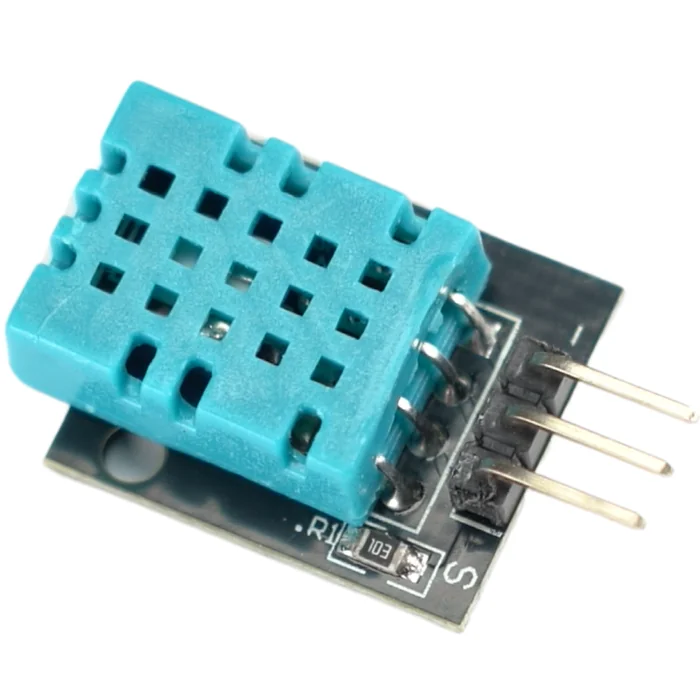
From the kit
DHT11 temperature and humidity sensor module
A digital measurement of two things at once. The blue case hides a humidity sensor and a thermistor, and a small chip converts both measurements into ready numbers straight away.
The module has three legs, labeled right on the board: S (signal – this is where you connect the digital pin), and power and ground on the other two (check the labels on your own module, because the order varies). The pull-up resistor, which you would have to add yourself to a bare DHT11 sensor, is already soldered onto the module's board here. You add nothing.
The DHT11 talks to the Arduino over one wire, with its own timing protocol. That is not something you could easily program from scratch, so you will use a ready-made library (more in the section “Building the circuit” and in the code below).
04
The LCD display and the I2C bus
A part from the catalog in Part 1 (item 6). There you only saw its picture. Now you finally get to connect it.
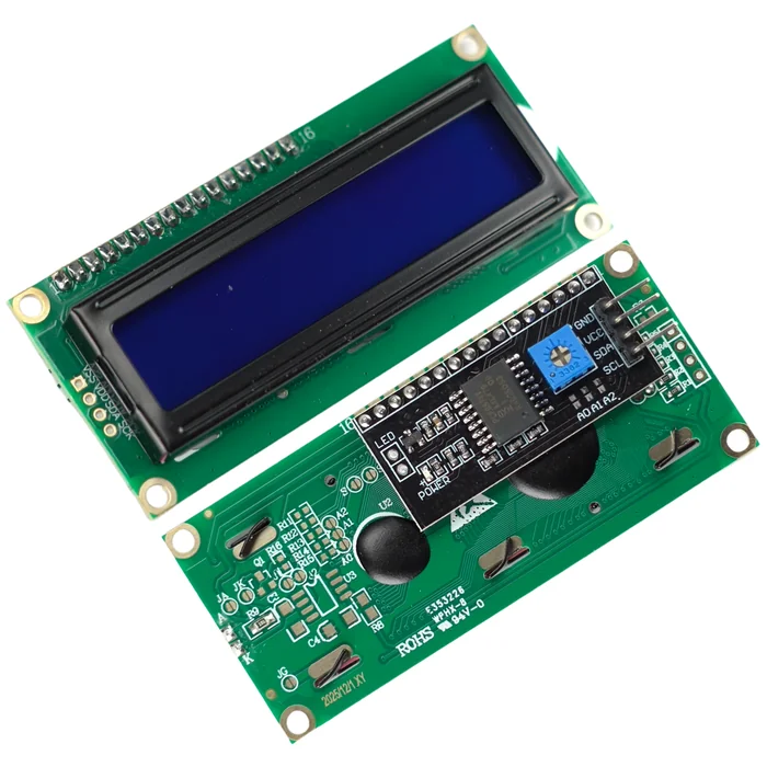
From the kit
2x16 LCD display 1602 + I2C adapter
Two lines of text, four wires. The display alone would need more than a dozen connections. The adapter attached to it turns them into four: power, ground and two data wires.
The adapter's four wires are GND (ground), VCC (power), SDA and SCL. The last two are I2C, the third communication interface announced in Part 4 (next to UART and the SPI from Part 16). The pins are at the back of the display, on the adapter itself. Do not look for them at the front, on the screen's board. I2C differs from SPI in one important thing: SPI needs a separate device-select wire (SS) for every connected module, while I2C tells devices apart by a unique address. Thanks to that, many different chips can share exactly the same two wires. On the R3 board these pins are labeled plainly as SDA and SCL.
The address of the display in this module is usually 0x27. That is what you will use in the code. If the screen stays empty even though the assembly is correct, the checklist below tells you what to check.
To drive the screen over I2C you need the LiquidCrystal_I2C library, and for the DHT11 a second one, SimpleDHT. Like MFRC522 in Part 16, both have already been added to the project of this lesson in the editor next to it.
05
Building the circuit
Nothing but ready-made modules. No resistors to calculate: three pairs of power wires and one signal wire for each module are enough.
What you need: the breadboard, the R3 board, the LM35DZ sensor, the DHT11 module, the LCD display with its I2C adapter, about 10 male-to-male jumper wires.
| Part | Leg / pin | Goes to | Note |
|---|---|---|---|
| LM35DZ | VCC | 5 V | – |
| LM35DZ | GND | “–” rail (GND) | – |
| LM35DZ | OUT | A0 | analog input |
| DHT11 | VCC/“+” | 5 V | – |
| DHT11 | GND/“–” | “–” rail (GND) | – |
| DHT11 | S | D2 | digital signal |
| LCD (I2C adapter) | GND | “–” rail (GND) | – |
| LCD (I2C adapter) | VCC | 5 V | – |
| LCD (I2C adapter) | SDA | the SDA pin of the R3 board | hardware I2C |
| LCD (I2C adapter) | SCL | the SCL pin of the R3 board | hardware I2C |
  LM35DZ (analog):
  A0 ── LM35DZ OUT         VCC from "+", GND from "-"

  DHT11 (digital, 1 wire):
  D2 ── DHT11 S            VCC from "+", GND from "-"

  LCD OVER I2C:
  SDA ── LCD SDA
  SCL ── LCD SCL           VCC from "+", GND from "-"
This is the whole circuit on the wiring diagram:
Step-by-step assembly
Build the circuit on the breadboard
Loading the 3D view...
Power the rails of the breadboard
With one jumper wire connect the 5V pin of the R3 board to the “+” rail, with another the GND pin to the “–” rail.
Order of assembly:
- 1Power the rails of the breadboard: a jumper wire from the 5 V pin of the R3 board to the “+” rail, a jumper wire from the GND pin to the “–” rail.
- 2Plug the LM35DZ into the breadboard (three legs in separate rows) and connect it with jumper wires:
VCCto the “+” rail,GNDto the “–” rail,OUTto pin A0. - 3Connect the DHT11 module:
VCCto the “+” rail,GNDto the “–” rail,Sto pin D2. - 4Connect the LCD display:
GNDto the “–” rail,VCCto the “+” rail,SDAto the SDA pin andSCLto the SCL pin of the R3 board. - 5Check everything once more. Only now plug in the USB cable.
06
The program step by step
Two sensors, two completely different libraries, one shared screen.
#include <Wire.h>
#include <LiquidCrystal_I2C.h>
#include <SimpleDHT.h>

const int lm35Pin = A0;
const int dht11Pin = 2;

LiquidCrystal_I2C lcd(0x27, 16, 2);  // the screen object: I2C address, number of columns, number of rows
SimpleDHT11 dht11(dht11Pin);

void setup() {
  lcd.init();       // resets the driver inside the display - ready for characters
  lcd.backlight();  // turns on the LED backlight at the back of the screen
}

void loop() {
  // LM35DZ - an analog sensor, we convert it ourselves
  int reading = analogRead(lm35Pin);
  float voltage = reading * (5.0 / 1023.0);
  float temperatureLM35 = voltage * 100.0;

  lcd.setCursor(0, 0);          // the "cursor" to column 0, row 0 (the top line)
  lcd.print("LM35: ");          // the driver draws every character from its own grid of dots
  lcd.print(temperatureLM35, 1);
  lcd.print("C   ");

  // DHT11 - a digital sensor, the result is ready
  byte temperatureDHT = 0;
  byte humidity = 0;
  int error = dht11.read(&temperatureDHT, &humidity, NULL);

  lcd.setCursor(0, 1);          // column 0, row 1 (the bottom line)
  if (error == SimpleDHTErrSuccess) {
    lcd.print("DHT: ");
    lcd.print(temperatureDHT);
    lcd.print("C ");
    lcd.print(humidity);
    lcd.print("%   ");
  } else {
    lcd.print("DHT: read error");
  }

  delay(2000);
}
Write this program in your browser
Tutorial on the left, editor on the right. Build your code and flash it to the board in one click, with nothing to install.
This program uses the libraries LiquidCrystal I2C 1.1.2, SimpleDHT 1.0.15. They are already added to the project in the editor next to the lesson.
Before you go on to the table, one thing that usually makes people curious: how does the screen “know” how to draw a letter, and what exactly do lcd.init() and lcd.backlight() do?
The backlight is an ordinary LED at the back of the screen. lcd.backlight() turns it on, so that there is anything to read at all. Every cell of the screen (you have 32 of them: 16 columns by 2 rows) is really a grid of tiny liquid crystal dots, usually 5 columns by 8 rows of dots in one cell. Liquid crystal does not shine by itself. It only lets the light of the backlight through or blocks it, dot by dot.
Inside the display itself sits the HD44780 driver (you already saw this name in Part 1, in the catalog description). It keeps the patterns of all the letters and digits in its memory, so it knows which dots to darken to make an “A”, for example. lcd.init() resets this driver at the start, so that it is ready to take characters. When you call lcd.print("A"), a whole chain of things happens: the Arduino sends the letter over SDA/SCL (I2C) to the adapter → the adapter (the PCF8574 chip, which you saw in the picture of the module) turns it into the signals that the HD44780 really needs → the HD44780 looks up the pattern of the letter “A” and darkens the right dots in the cell where the “cursor” is standing. lcd.setCursor(column, row) is what moves this cursor. Every next lcd.print() draws further on, one cell after another, the way the carriage moves in a typewriter.
| Instruction | What it does |
|---|---|
#include <Wire.h> | Arduino's built-in library for I2C communication – without it LiquidCrystal_I2C has no way to talk to the screen |
#include <LiquidCrystal_I2C.h> and #include <SimpleDHT.h> | libraries from outside the standard Arduino set – both have to be added to the project, like MFRC522 in Part 16 (the project of this lesson already has them) |
LiquidCrystal_I2C lcd(0x27, 16, 2); | creates the screen object: I2C address, number of columns, number of rows |
lcd.init() and lcd.backlight() | starts the display and turns on the backlight – you call them once, in setup() |
analogRead(lm35Pin) | reads the raw voltage from the LM35 as a number 0–1023 |
voltage * 100.0 | the LM35 gives 10 mV per degree, so 1 V of voltage is 100°C |
dht11.read(&temperatureDHT, &humidity, NULL) | asks the DHT11 – fills in both variables and returns an error code |
lcd.setCursor(0, 1) | moves the text “cursor” to the start of the second row of the screen (rows are numbered from 0) |
Flash the code to the board through FlashESP.com, as in the earlier parts. On the screen you will see two lines: the top one with the LM35 reading, the bottom one with the temperature and humidity from the DHT11. Hold a finger on the case of the LM35 or breathe on the DHT11. After a moment you will see the readings change, each at its own pace.
The two sensors will almost certainly not show the same temperature. A difference of 1–2°C is not an error, just the difference in accuracy between them. It is a good chance to see live what “the accuracy of a sensor” means: the number in the specification stops being abstract.
Conclusions: which sensor to choose?
| LM35DZ | DHT11 | |
|---|---|---|
| Measures | temperature only | temperature and humidity |
| Accuracy | higher, about ±0.5–1°C | lower, ±2°C (humidity ±5%) |
| Reading speed | instant, no limits | at most once every second or so |
| Work in the code | you convert the voltage to degrees | the result comes ready from the library |
| Extra library | needs none | needs an external one (SimpleDHT) |
| Size | small, three legs | a slightly bigger module |
When to reach for the LM35DZ: when accuracy and a quick reaction matter and humidity does not – for example a precise thermostat, an overheating sensor, or measuring temperature in an experiment where you want a reading at any moment, without waiting. Fewer things that can fail: no library, no protocol, just a voltage and a simple formula.
When to reach for the DHT11: when you need the humidity too and do not care about readings more often than once a second – a home weather station, or a monitor for a greenhouse or a terrarium, where the general trend matters (“it is dry, time to add some moisture”) and not a single, perfectly precise measurement. You pay for it with a slower reading, lower accuracy and an extra library in the project.
In short: the LM35DZ for jobs where the precision and speed of one quantity matter; the DHT11 where the range of what you measure (two quantities at once) matters more than the last decimal place.
Build checklist
Tick them off one by one. Your progress is saved in this browser.
0 / 12
Rules worth remembering
- 1
The LM35DZ has three legs in a fixed order.
Mixing up
VCCandGNDcan damage the sensor. Check the order against the flat side of the case. - 2
Do not ask the DHT11 more often than once a second.
Readings taken too often end in an error. Leave
delay(2000)or a longer one in the code. - 3
We rewire the circuit with the power disconnected.
Pull out the USB cable, move the jumper wires, check once more, and only then plug it back in.
Projects
None of the projects below needs anything extra: everything is already in the kit. They go roughly from the easiest to the most ambitious.
- 1
An LM35 thermometer on the LCD
Easy- What you will use
- the LM35DZ + the LCD (no DHT11)
- What you will learn
- simplifying the circuit to one sensor
- 2
An overheating alarm
Easy- What you will use
- the LM35DZ + the buzzer from Part 6
- What you will learn
- reacting with sound when a threshold is crossed
- 3
A humidity warning
Medium- What you will use
- the DHT11 + an LED with a resistor
- What you will learn
- reacting to a humidity threshold instead of a temperature one
- 4
An averaged temperature
Medium- What you will use
- the LM35DZ
- What you will learn
- averaging several measurements instead of trusting one reading
- 5
A conditions logger
Challenging- What you will use
- the DHT11 + the EEPROM from Part 14
- What you will learn
- saving regular readings in permanent memory
Summary
This part showed two different philosophies of measuring the same physical quantity: the LM35DZ gives a raw voltage that you convert yourself, and the DHT11 gives a ready result, at the price of waiting between readings. You also added the first LCD display of this series and met I2C, the third way of talking to modules after UART and SPI, this time one in which many devices share the same two wires. The same SDA/SCL pair will come back when more I2C modules appear in the coming parts.