XXL Kit for Arduino · Lock
Part 16 The RFID module and a relay: a card lock
- Beginner
- Ages 8+
- about 60 min
A card instead of a button. In this part you will build the electronic version of a lock: you hold a card or a key fob up to the RFID-RC522 reader, and the reader tells the Arduino “something is in range”. The Arduino answers with a relay, an electronic switch that can turn on a circuit completely independent of the R3 board itself.
Who is it for? For children and teenagers aged 8 and up, for teachers, and for adults who have done Parts 4 and 5: it helps to know the LED with its resistor and digital pins used as outputs.
01
How an electronic lock works
Two states, one rule: as long as you hold nothing up to the reader, the output circuit is off.
| State | Red LED | Green LED | Relay | What triggers it |
|---|---|---|---|---|
| Standby | lit | off | off | the starting state, and the one it returns to after every opening |
| Access granted | off | lit | on for 3 seconds | a card or a key fob in range of the reader |
This is a simplified version of a real RFID lock. It does not check which card it is, only whether any card at all is in range. Recognizing one particular card is one of the projects at the end of this part.
02
The RFID-RC522 reader
A part from the catalog in Part 1 (item 20). There you only saw its picture. Now you finally get to connect it.
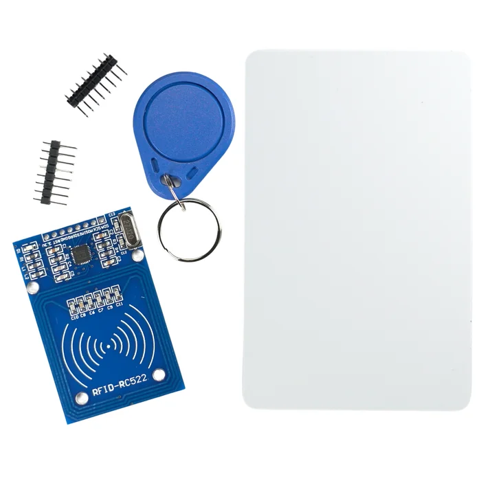
From the kit
RFID-RC522 reader + card + key fob
It recognizes a card without touching it. The reader has a small antenna that “powers” the card or the key fob by radio for a moment. That is why it works from a few centimeters away, not from across the room, and why the card needs no battery of its own.
Important before you start the assembly: the reader comes with its pins not soldered on. In the bag with the module there are two separate strips of pins. Pick the one whose shape suits you better and solder it to the reader's board, so that the connection is solid. This is the first part in this series that needs it: until now no other module needed soldering. If you have no soldering iron, or have never used one, you can push male jumper wires into the pin holes without soldering. It will work, but such a connection is very delicate (a nudge is enough to break it), and the SPI signal itself is less accurate.
The reader talks to the Arduino over SPI. In the table of interfaces in Part 4 you saw this name with a promise: “you will meet it with the modules that need it”. This is that moment. SPI is a way of sending data over four wires: SS (chooses the device when more than one hangs on the bus; on the reader it is marked SDA), MOSI (data from the Arduino to the device), MISO (data from the device to the Arduino) and SCK (the clock, which beats the rhythm). On the R3 board MOSI, MISO and SCK are tied by the hardware to pins 11, 12 and 13, and you cannot move them to other pins. SS you can choose yourself. In this project it is D10.
To work with the reader you need the MFRC522 library. In the editor next to the lesson it has already been added to your project, so you do not have to install anything. If you ever write a program like this in a project of your own, you add the library on the project page with the Manage Libraries button, searching for MFRC522.
03
The relay
A part from the catalog in Part 1 (item 31): an electromagnetic switch that is pressed by the Arduino, not by your finger.
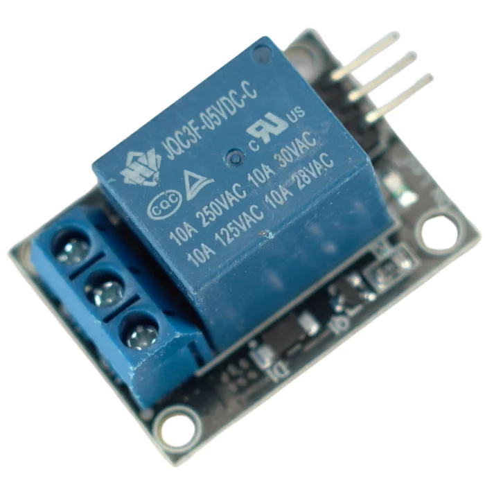
From the kit
5V 10A relay module
A small coil switches a big circuit. A signal from a digital pin turns on an electromagnet. The electromagnet pulls a little metal tongue and physically closes another, completely isolated circuit. You will hear the typical “click”.
The module has two sides: the control side (VCC, GND, IN – what you connect to the R3 board) and the switched side (the screws COM, NO, NC – what it switches). In this part we connect nothing to the screw terminal. It is enough to hear the “click” and see the LED on the module to confirm that the relay has worked. We will come back to COM/NO/NC later in the series, when the relay really switches something.
04
Reminder: the LED and the resistor
No new hardware apart from the reader and the relay. The rest are parts you already know from Parts 4 and 5.
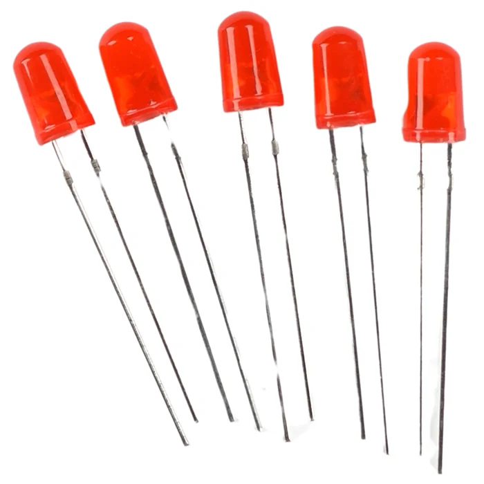
From the kit
LED (red) – standby
The anode (the longer leg) always goes through a resistor. The full explanation of polarity is in Parts 4 and 5.
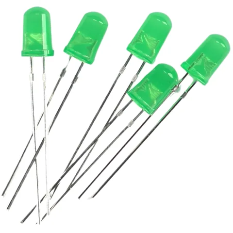
From the kit
LED (green) – access granted
The same part as the red one, in a different color. It lights up for the 3 seconds during which the relay is on.
From the kit
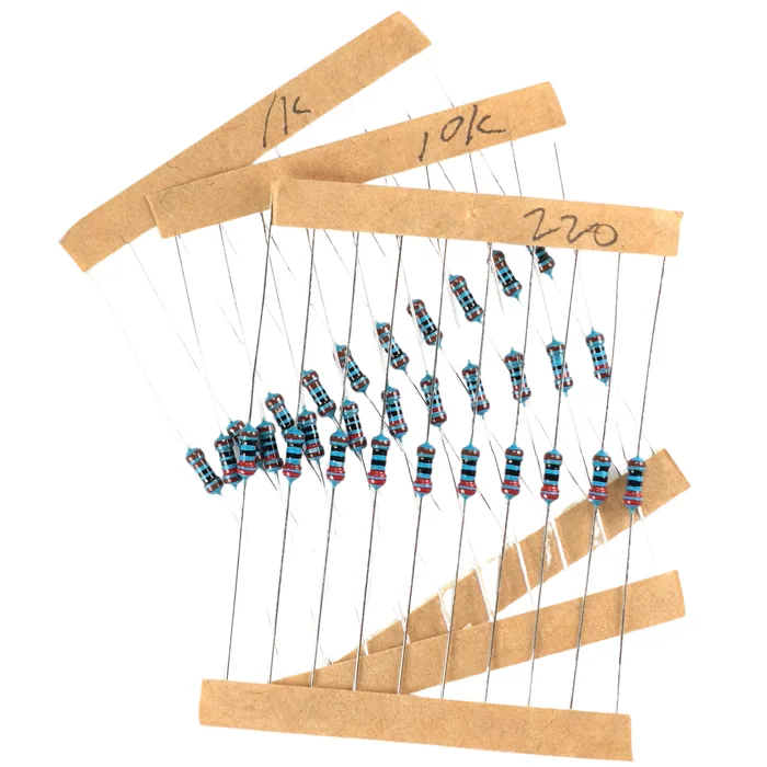
220 Ω resistor
One for each LED, always in series. Without it the LED burns out very quickly.
05
Building the circuit
More connections than usual, but each one goes to one precisely described place.
What you need: the breadboard, the R3 board, the RFID-RC522 reader, the relay module, two LEDs (a red one and a green one), two 220 Ω resistors, about 12 male-to-male jumper wires.
Before you start connecting jumper wires, check that the reader's pins are already soldered on (see the section above).
| Part | Leg / pin | Goes to | Note |
|---|---|---|---|
| RFID reader | 3.3V | the 3.3V pin of the R3 board | not 5 V – the module will be damaged |
| RFID reader | GND | “–” rail (GND) | – |
| RFID reader | RST | D9 | resets the reader |
| RFID reader | SDA (SS) | D10 | chooses the device – the next pin after RST |
| RFID reader | MOSI | D11 | hardware SPI – the next pin after SDA |
| RFID reader | MISO | D12 | hardware SPI – the next pin after MOSI |
| RFID reader | SCK | D13 | hardware SPI – the next pin after MISO |
| RFID reader | IRQ | not connected | not used in this project |
| Relay | VCC | 5 V | power for the coil |
| Relay | GND | “–” rail (GND) | – |
| Relay | IN | D8 | the signal that turns it on |
| 220 Ω resistor (red) | one end | pin D6 | – |
| 220 Ω resistor (red) | other end | anode of the red LED | – |
| Red LED | cathode (shorter leg) | “–” rail (GND) | – |
| 220 Ω resistor (green) | one end | pin D7 | – |
| 220 Ω resistor (green) | other end | anode of the green LED | – |
| Green LED | cathode (shorter leg) | “–” rail (GND) | – |
The reader's five signal pins, RST, SDA, MOSI, MISO and SCK, go in order to five pins in a row on the board: D9, D10, D11, D12, D13. That makes it easy to check at the end that you have not missed any.
  RFID-RC522 READER (SPI):
  3.3V ── reader 3.3V      NOT 5V!
  GND  ── reader GND
  D9   ── reader RST
  D10  ── reader SDA (SS)
  D11  ── reader MOSI
  D12  ── reader MISO
  D13  ── reader SCK

  RELAY:
  D8 ── relay IN           the relay's VCC and GND from the breadboard rails

  STANDBY LED (red, through 220 Ω):
  D6 ──[ 220 Ω ]──►|── GND

  ACCESS LED (green, through 220 Ω):
  D7 ──[ 220 Ω ]──►|── GND
This is the whole circuit on the wiring diagram:
Step-by-step assembly
Build the circuit on the breadboard
Loading the 3D view...
Power the rails of the breadboard
With one jumper wire connect the 5V pin of the R3 board to the “+” rail, with another the GND pin to the “–” rail.
Order of assembly:
- 1Power the rails of the breadboard: a jumper wire from the 5 V pin of the R3 board to the “+” rail, a jumper wire from the GND pin to the “–” rail.
- 2Plug in the RFID reader and connect its pins with jumper wires:
3.3Vto the 3.3V pin of the R3 board (not to the “+” rail, which has 5 V),GNDto the “–” rail, and then the five signal pins in order to five pins in a row on the board:RSTto D9,SDAto D10,MOSIto D11,MISOto D12,SCKto D13. - 3Plug in the relay module:
VCCto the “+” rail,GNDto the “–” rail,INto D8. - 4Plug in a 220 Ω resistor between pin D6 and a free row, plug the anode of the red LED into the same row, and connect the cathode to the “–” rail with a jumper wire.
- 5Repeat step 4 for the green LED: the resistor between pin D7 and its anode, the cathode to the “–” rail.
- 6Check everything once more. Only now plug in the USB cable.
06
The program step by step
SPI.begin() and reader.PCD_Init() at the start, and then in every loop one question: “is there a card?”
Before you see the whole code, here are two things that are new compared with the Servo from Part 7 or the EEPROM from Part 14.
First: where MFRC522.h comes from. Servo and EEPROM are libraries built into Arduino. They were available at once, with no extra step. MFRC522 was written by somebody else, and it has to be added to the project: in the project of this lesson, FlashESP has already done that for you. It is the first library in this series from outside Arduino that has to be added to the project: Servo and EEPROM worked without this step. It will probably not be the last. In the coming parts more modules are waiting, each with its own external library.
Second: the line MFRC522 reader(ssPin, rstPin);. It is not a function call. It creates an object: your own, named “copy” of all the logic that handles the reader, assigned straight away to your SS and RST pins. You saw exactly the same pattern with the servo (Servo arm;). The difference is that the servo needed no data when it was created, while the reader needs to know its pins right away. From now on you write every command to the reader with a dot after the object's name: reader.PCD_Init(), reader.PICC_IsNewCardPresent(), exactly like servo.attach() or servo.write().
The function names have two prefixes that keep coming back. It is worth decoding them instead of treating them as random letters: PCD_ is about the reader itself (for example PCD_Init() – start the reader), and PICC_ is about the card you hold up to it (for example PICC_IsNewCardPresent() – is a card in range). The rest of the name usually says plainly what the function does.
#include <SPI.h>
#include <MFRC522.h>

const int ssPin = 10;            // SDA / SS of the RFID reader
const int rstPin = 9;            // RST of the RFID reader
const int relayPin = 8;
const int greenLedPin = 7;
const int redLedPin = 6;

MFRC522 reader(ssPin, rstPin);

void setup() {
  SPI.begin();
  reader.PCD_Init();

  pinMode(relayPin, OUTPUT);
  pinMode(greenLedPin, OUTPUT);
  pinMode(redLedPin, OUTPUT);

  digitalWrite(relayPin, LOW);
}

void loop() {
  digitalWrite(redLedPin, HIGH);         // standby
  digitalWrite(greenLedPin, LOW);

  if (!reader.PICC_IsNewCardPresent()) {
    return;                              // nothing in range - go back to the start of the loop
  }
  if (!reader.PICC_ReadCardSerial()) {
    return;                              // detected, but the reading failed
  }

  // card read - grant access
  digitalWrite(redLedPin, LOW);
  digitalWrite(greenLedPin, HIGH);
  digitalWrite(relayPin, HIGH);
  delay(3000);
  digitalWrite(relayPin, LOW);

  reader.PICC_HaltA();                   // end the conversation with the card
}
Write this program in your browser
Tutorial on the left, editor on the right. Build your code and flash it to the board in one click, with nothing to install.
| Instruction | What it does |
|---|---|
#include <SPI.h> | Arduino's built-in library for SPI communication – without it MFRC522 has no way to talk to the reader |
#include <MFRC522.h> | the reader's library, from outside the standard Arduino set – unlike Servo or EEPROM, it has to be added to the project (the project of this lesson already has it) |
MFRC522 reader(ssPin, rstPin); | creates the reader object assigned to your SS and RST pins – from now on you control it through reader.something() |
SPI.begin() | turns on the general SPI bus – a shared “channel” over which different SPI devices can talk |
reader.PCD_Init() | starts this particular RC522 module (PCD = the reader itself) – you call it once, in setup() |
reader.PICC_IsNewCardPresent() | asks: is any card (PICC) in range? It returns true/false and does not read anything yet |
reader.PICC_ReadCardSerial() | only this really reads the data of the detected card – two separate steps, because “something detected” is not the same as “read correctly” |
reader.PICC_HaltA() | “hangs up the phone” – ends the conversation with this card, so that the reader resets and is ready to detect the next one |
digitalWrite(relayPin, HIGH) | turns the relay on – you will hear a “click” |
This program uses the library MFRC522 1.4.12. It is already added to the project in the editor next to the lesson.
Flash the code to the board through FlashESP.com, as in the earlier parts. Hold a card or a key fob a few centimeters from the reader's antenna (the flat side with the drawing of waves): the red LED goes out, the green one lights up, the relay “clicks”, and after 3 seconds it returns to standby.
If the relay “clicks” exactly the other way round, turning on right after you flash the code and off when you hold up a card, it is not a bug in the code. Some relay modules have inverted logic on the IN input: change HIGH to LOW in the code where the relay is turned on and check again.
Bonus: take a peek at the UID of your card
A number you cannot just fake. Every card and key fob has a tiny chip inside, and in the chip a number stored for good: the UID (Unique IDentifier). This number was burned into the chip at the factory, much like a serial number stamped in metal. It cannot be changed or erased. When you hold a card up to the reader, what happens is what you already know from the section about the reader above: the antenna “wakes up” the chip by radio for a moment, and the chip answers by sending back just this number. Nothing more, no “name” and no photo. A city transit card, an office pass and a hotel key work on exactly this principle: the reader at the door is always the same, and only the number stored in your card is different.
In the main code of this part we did not check at all what the number is: every card or key fob opened the lock. This extra program lets you finally see the number with your own eyes. That is the first step toward a lock that recognizes your card and lets nobody else in, which is exactly what the project “A lock for one chosen card” below does. You run the code on exactly the same circuit as above. Do not rewire anything.
#include <SPI.h>
#include <MFRC522.h>

const int ssPin = 10;
const int rstPin = 9;

MFRC522 reader(ssPin, rstPin);

void setup() {
  Serial.begin(9600);
  SPI.begin();
  reader.PCD_Init();
  Serial.println("Hold up a card or a key fob...");
}

void loop() {
  if (!reader.PICC_IsNewCardPresent()) {
    return;
  }
  if (!reader.PICC_ReadCardSerial()) {
    return;
  }

  Serial.print("UID: ");
  for (byte i = 0; i < reader.uid.size; i++) {
    Serial.print(reader.uid.uidByte[i], HEX);
    Serial.print(" ");
  }
  Serial.println();

  reader.PICC_HaltA();
}
Serial.begin(9600) opens the serial port. You add it once, in setup(). reader.uid.size says how many bytes the UID of this particular card has (usually 4), and reader.uid.uidByte[i] are the bytes of that number, one after another. The for loop prints them one by one in the hexadecimal system (HEX). You will see the result in the Serial Monitor: the “Serial Monitor” tab below the editor, next to “Building & flashing” (we showed it in Parts 2 and 3). Set its speed to 9600 baud and click “Connect”: everything the program prints with Serial.print() appears there, line by line. Do not look for it in the “Full compiler log”: that only shows how the program was built. Write down the UID you see. It will come in handy in the project “A lock for one chosen card” below.
Build checklist
Tick them off one by one. Your progress is saved in this browser.
0 / 16
Rules worth remembering
- 1
Connect the RFID-RC522 reader to 3.3 V, never to 5 V.
Power from the “+” rail (5 V) can damage it.
- 2
The relay is not for connecting 230 V mains voltage.
In this part, and in every other part of this series, we never connect the relay's screw terminal to a wall socket. That is a job for an electrician, not for a learning kit.
- 3
An LED always goes with a 220 Ω resistor, and it has polarity.
The longer leg (anode) to the resistor, the shorter one (cathode) to “–”.
- 4
We rewire the circuit with the power disconnected.
Pull out the USB cable, move the jumper wires, check once more, and only then plug it back in.
Projects
None of the projects below needs anything extra: everything is already in the kit. They go roughly from the easiest to the most ambitious.
- 1
A card detector
Easy- What you will use
- the RFID reader + an LED (no relay)
- What you will learn
- reading a card without controlling anything else
- 2
An RFID doorbell
Easy- What you will use
- the RFID reader + the passive buzzer from Part 6
- What you will learn
- swapping the relay for another kind of output with the same logic
- 3
An entry counter
Medium- What you will use
- the RFID reader + an LED
- What you will learn
- counting events in a variable, as in Part 15
- 4
A lock with a timed lockout
Medium- What you will use
- the RFID reader + the relay
- What you will learn
- measuring time with the
millis()function instead of the blockingdelay()
- 5
A lock for one chosen card
Challenging- What you will use
- the RFID reader + the relay + 2 LEDs
- What you will learn
- comparing the UID of the card that was read (
reader.uid.uidByte) with a stored pattern
Summary
This part added two things to your toolbox: the first module that communicates over SPI, and the first actuator that switches a circuit electrically isolated from the Arduino. Together the RFID-RC522 reader and the relay give you exactly what real access control systems are built on: something that recognizes a permission, and something that physically turns something on because of it. In the coming parts these two building blocks, recognizing and switching, will come back in more and more complex circuits.