XXL Kit for Arduino · Alarm
Part 15 The vibration sensor: an alarm system
- Beginner
- Ages 8+
- about 45 min
A new section, a new kind of input. Until now your circuit reacted only to what you did to it yourself: pressing a button, turning a knob. The SW-520D vibration sensor reacts to something nobody can predict in advance: a shake, a knock, someone trying to move the circuit. In this part you will use it to build a simple burglar alarm system. You arm and disarm it with a button, and it reports a break-in with an LED and a siren from the buzzer.
Who is it for? For children and teenagers aged 8 and up, for teachers, and for adults who have done Parts 4–6: it helps to know the button with INPUT_PULLUP and the passive buzzer with tone().
01
How an alarm system works
Three states, one job: making sure nobody touches the circuit while you are out of the room.
Real home alarms work exactly like the one you are about to build, only on a bigger scale. The system has three states, and the button and the sensor switch it between them:
| State | LED | Buzzer | What causes it |
|---|---|---|---|
| Disarmed | off | quiet | the starting state, or the button pressed during an alarm |
| Armed | on all the time | quiet | the button pressed in the disarmed state |
| Alarm | blinks fast | siren (two alternating tones) | the vibration sensor felt a shake in the armed state |
The key rule: the sensor matters only in the armed state. When the alarm is disarmed, you can shake the circuit as much as you like and nothing will happen. It is just like a real home: the alarm reacts to movement only when you switch it on as you leave.
02
The SW-520D vibration sensor
A part from the list in Part 1 (item 27). There you only saw its picture; now you finally get to connect it.
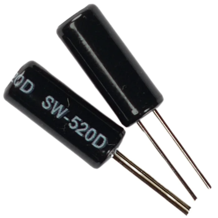
From the kit
SW-520D vibration sensor
A button that presses itself. Inside there is a tiny spring or ball which, when shaken, connects the two legs of the case for a moment. Electrically it behaves exactly like the tact switch from Part 5, except that a shake presses it instead of a finger.
You connect it exactly like a button: one leg to a digital pin with INPUT_PULLUP, the other to “–” (GND). The difference only shows up when you read it: a shake rarely gives one clean click. Usually you get a series of several fast LOW/HIGH switches within a fraction of a second, because the spring bounces around inside the case. For an alarm that is actually handy: any single LOW is enough to decide that something moved.
03
Reminder: the button, the LED and the buzzer
No new hardware apart from the sensor. Everything else you already know from earlier parts.
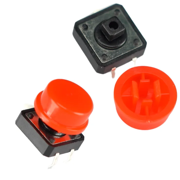
From the kit
Tact switch – arms and disarms
A digital input with INPUT_PULLUP: pressed, it gives LOW; released, HIGH. The full explanation is in Part 5.
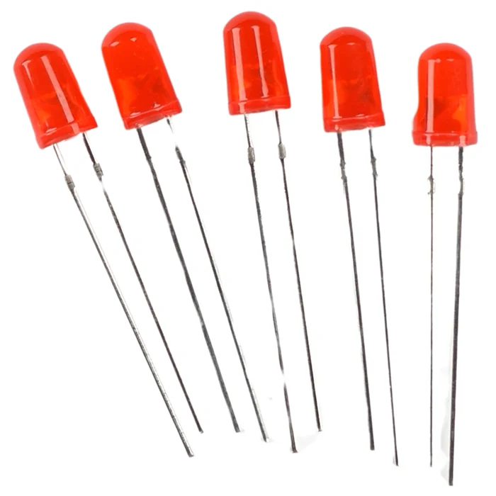
From the kit
LED (red) – alarm status
The anode (longer leg) always goes through a resistor. The full explanation of polarity is in Parts 4 and 5.
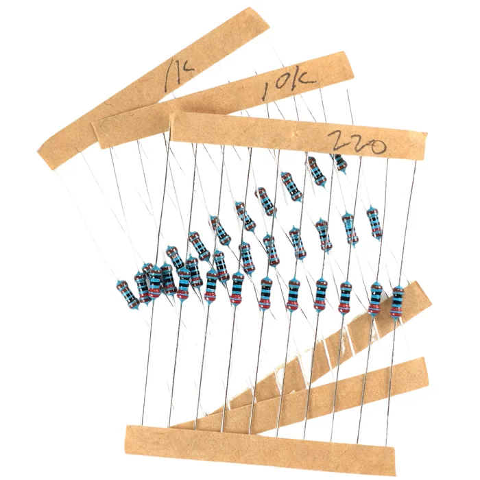
From the kit
220 Ω resistor
It goes in series with the LED, always. Without it, the LED that shines all the time in the armed state would burn out very quickly.
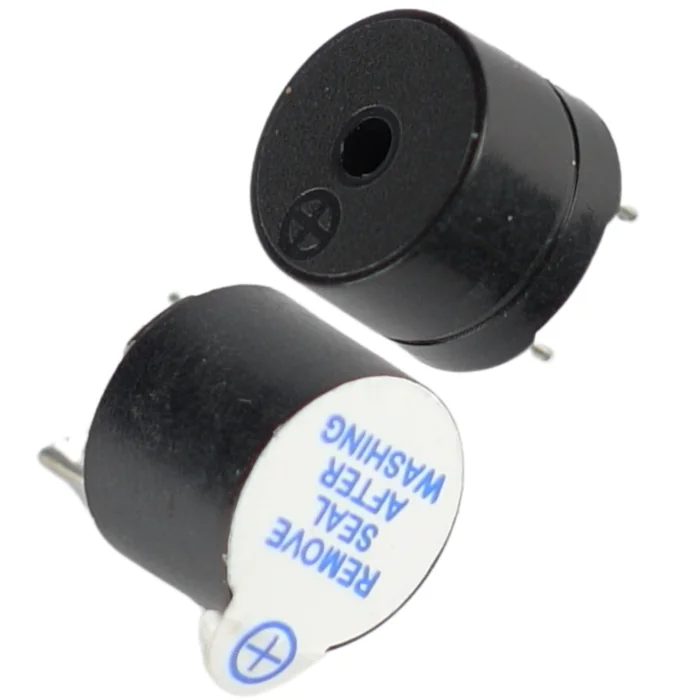
From the kit
Passive buzzer – siren
Controlled with the tone() function: two alternating tones make the classic siren sound. The full explanation is in Part 6.
04
Building the circuit
Four parts, one idea. In a moment you will shake the circuit and hear that it really works.
What you need: the breadboard, the R3 board, the SW-520D vibration sensor, a tact switch button, an LED (red), a 220 Ω resistor, the passive buzzer, 7–8 male-to-male jumper wires.
| Part | Leg / pin | Goes to | Note |
|---|---|---|---|
| Vibration sensor | leg 1 | D3 | in the code: INPUT_PULLUP |
| Vibration sensor | leg 2 | “–” rail (GND) | shake = a series of LOWs |
| Button | leg 1 | D2 | in the code: INPUT_PULLUP |
| Button | leg 3 (diagonally opposite) | “–” rail (GND) | pressed = LOW |
| 220 Ω resistor | one end | pin 9 | limits the LED's current |
| 220 Ω resistor | other end | the row with the LED's anode | – |
| LED (red) | anode (longer leg) | the row with the resistor | plus side |
| LED (red) | cathode (shorter leg) | “–” rail (GND) | minus side |
| Passive buzzer | “+” (or the longer leg) | pin 8 | the signal from tone() |
| Passive buzzer | “–” | “–” rail (GND) | – |
  VIBRATION SENSOR (detects a shake):
  D3 ──┤ sensor ├── GND         INPUT_PULLUP in the code, shake = a series of LOWs

  BUTTON (arms / disarms):
  D2 ──┤ button ├── GND         INPUT_PULLUP in the code, pressed = LOW

  LED (alarm status, through 220 Ω):
  9 ──[ 220 Ω ]──►|── GND       anode (longer leg) on the resistor's side

  BUZZER (siren):
  8 ──┤ buzzer ├── GND          "+" (or the longer leg) on the side of pin 8
This is the whole circuit built on the breadboard:
Step-by-step assembly
Build the circuit on the breadboard
Loading the 3D view...
Power the rails of the breadboard
With one jumper wire connect the 5V pin of the R3 board to the “+” rail, with another the GND pin to the “–” rail.
Order of assembly:
- 1Power the rails of the breadboard: a jumper wire from the 5 V pin of the R3 board to the “+” rail, and a jumper wire from the GND pin to the “–” rail.
- 2Plug in the vibration sensor: one leg with a jumper wire to pin D3, the other to the “–” rail.
- 3Plug in the button straddling the groove in the middle of the breadboard: one leg to pin D2, the leg diagonally opposite to the “–” rail.
- 4Plug in the 220 Ω resistor: one end in a row connected by a jumper wire to pin 9, the other in a free row.
- 5Plug in the LED: the anode (longer leg) in the row with the other end of the resistor, the cathode (shorter leg) with a jumper wire to the “–” rail.
- 6Plug in the buzzer: “+” (or the longer leg) to pin 8, the other leg to the “–” rail.
- 7Check everything once more. Only now plug in the USB cable.
05
The program step by step
Remember switch from Part 3? This is the perfect chance to use it for real: three states, three branches.
const int sensorPin = 3;     // SW-520D vibration sensor
const int buttonPin = 2;     // the button arms / disarms the alarm
const int ledPin = 9;        // red LED - alarm status
const int buzzerPin = 8;     // passive buzzer - siren

const int DISARMED = 0;
const int ARMED = 1;
const int ALARM = 2;

int state = DISARMED;               // we start disarmed
int previousState = HIGH;           // INPUT_PULLUP: released = HIGH

void setup() {
  pinMode(sensorPin, INPUT_PULLUP);
  pinMode(buttonPin, INPUT_PULLUP);
  pinMode(ledPin, OUTPUT);
  pinMode(buzzerPin, OUTPUT);
}

void loop() {
  // 1. Read the button with debounce - it switches the state of the alarm
  int buttonState = digitalRead(buttonPin);
  if (buttonState == LOW && previousState == HIGH) { // it has just been pressed
    if (state == DISARMED) {
      state = ARMED;      // arm
    } else {
      state = DISARMED;   // disarm - this works during the alarm too
    }
    delay(20);            // wait out the contact bounce of the button
  }
  previousState = buttonState;

  // 2. Armed and the sensor detected a shock -> alarm
  if (state == ARMED && digitalRead(sensorPin) == LOW) {
    state = ALARM;
  }

  // 3. React according to the current state
  switch (state) {
    case DISARMED:
      digitalWrite(ledPin, LOW);
      noTone(buzzerPin);
      break;

    case ARMED:
      digitalWrite(ledPin, HIGH); // the LED shines all the time - the alarm is on guard
      noTone(buzzerPin);
      break;

    case ALARM:
      digitalWrite(ledPin, HIGH);
      tone(buzzerPin, 1000);
      delay(150);
      digitalWrite(ledPin, LOW);
      tone(buzzerPin, 1600);
      delay(150);
      break;
  }
}
Write this program in your browser
Tutorial on the left, editor on the right. Build your code and flash it to the board in one click, with nothing to install.
| Instruction | What it does |
|---|---|
pinMode(sensorPin, INPUT_PULLUP) | the same trick as with the button – the sensor works like a button that presses itself |
if (state == ARMED && digitalRead(sensorPin) == LOW) | the alarm goes off only when the system is armed – when disarmed, it ignores shakes |
switch (state) | three branches instead of three separate ifs – the same mechanism as in Part 3 |
tone(buzzerPin, 1000) / tone(buzzerPin, 1600) | two alternating tones make the classic siren sound |
button checked before switch | thanks to this it works in every state, also during the alarm – it disarms it at once |
Flash the code to the board through FlashESP.com, just as in the earlier parts. Press the button once: the LED lights up and stays on, and the alarm is armed. Shake the sensor (or gently tap the breadboard): the LED starts to blink, and the buzzer wails in two alternating tones. Press the button again: silence, the LED goes out, and the alarm is back in the disarmed state.
If the alarm goes off by itself, without any shake, it is almost certainly not a mistake in the code but the position of the sensor: see the checklist below.
Build checklist
Tick them off one by one. Your progress is saved in this browser.
0 / 14
Rules worth remembering
- 1
An LED always gets a 220 Ω resistor.
In the armed state it shines nonstop: without a resistor it would burn out even faster than when it only blinks.
- 2
An LED has polarity.
The longer leg (anode) to the resistor, the shorter one (cathode) to “–”.
- 3
The vibration sensor “shakes” electrically, and the way it lies matters.
One shake usually gives several fast
LOW/HIGHswitches, not one clean click. For an alarm that does no harm: oneLOWis enough to set it off. But at the wrong angle the ball inside can rest on the contacts for good. If the alarm goes off for no reason, simply turn the sensor. - 4
We rewire the circuit with the power disconnected.
Pull out the USB cable, move the jumper wires, check once more, and only then plug it back in.
Projects
None of the projects below needs anything extra: everything is already in the kit. They go roughly from the easiest to the most ambitious.
- 1
A silent night alarm
Easy- What you will use
- the vibration sensor + an LED (no buzzer)
- What you will learn
- switching off one output of the state machine without touching the rest of the logic
- 2
An alarm that gives you time to leave
Easy- What you will use
- the vibration sensor + the button
- What you will learn
- adding a delay after arming before the sensor starts to react – just like in a real home
- 3
A shake counter
Medium- What you will use
- the vibration sensor + an LED
- What you will learn
- counting input events in a variable and showing the result by blinking
- 4
A two-zone alarm
Medium- What you will use
- 2x vibration sensor (there are two in the kit)
- What you will learn
- handling several inputs of the same kind on separate pins
- 5
Disarming with a double click
Challenging- What you will use
- the button + the vibration sensor
- What you will learn
- measuring the time between presses with the
millis()function
Summary
This part opened a new section: sensors that react to something nobody can predict in advance. Electrically, the SW-520D vibration sensor behaves like a button, but you decide in the code when its signal matters. That is why there is a state machine with three branches instead of a simple if. The same structure, disarmed / armed / alarm, will come back in this series more than once, each time guarding something different.