XXL Kit for Arduino · Score
Part 14 Snake with a scoreboard
- Beginner
- Ages 8+
- about 90 min
This is the finale of the game section. You combine Snake from Part 12 with the register from Part 13 and add the thing no real game can do without: a score. One 74HC595 register takes turns driving the matrix and the 1-digit display, and the high score survives even when the power is switched off, because it goes into the EEPROM memory.
Who is it for? For children and teenagers aged 8 and up, for teachers, and for adults who have done Parts 10–13. This is the most complex circuit in the series. If one of the building blocks (the matrix, the joystick, the register) misbehaves on its own, go back to its part before you start putting the whole thing together.
01
What we are building
A game without a score gets boring fast. This part gives Snake what it was missing: a number that grows, and a high score that it remembers.
The hardware stays exactly as in Part 12, plus one shift register from Part 13. What changes is what the program does:
- you still play the snake game on the matrix, unchanged,
- the 1-digit display next to it shows the current score (how many fruits you have eaten),
- when the score goes above 9, the dot lights up: that is your way of showing a two-digit number on a single digit,
- after you lose, if you have beaten the high score, the new value goes into the EEPROM memory and survives even when you pull the plug,
- hold down the joystick button to see the high score instead of the current score. In Part 12 there was no free pin for it; here there is one.
There are pins to spare. After adding the register, the display and the button, three are still free (D11, A0, A1), enough for another project from the checklist at the end.
02
What stays from Parts 10–13
Four parts you already know. None of them changes its role; the register just gets an extra job.
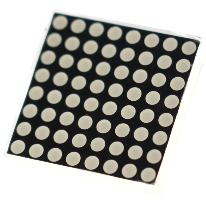
From the kit
8x8 LED matrix
The game screen, unchanged. The rows still go straight to the pins, exactly as in Parts 10 and 12.
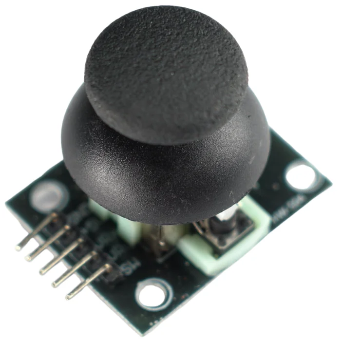
From the kit
Joystick
The controls, unchanged (X axis on A5, Y axis on A4, as in Part 12). New: the SW button finally has a free pin.
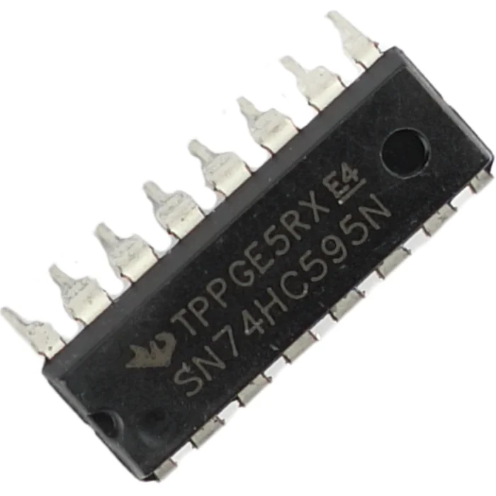
From the kit
74HC595 shift register
The hardware is the same as in Part 13: the same three control pins. It gets a second job: besides the display, it also drives the columns of the matrix.
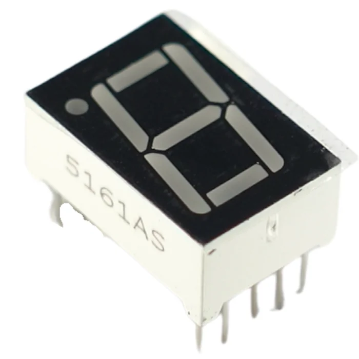
From the kit
1-digit 7-segment display
The segments are connected as in Part 9, but without resistors of their own. The display borrows them from the matrix: the two never shine at the same moment, so one set of eight is enough.
From the kit
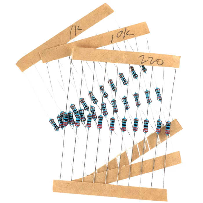
Eight 220 Ω resistors
The same set as in Parts 10 and 13. Now each one feeds two things at once: one column of the matrix and one segment of the display.
03
New: one register, two devices
The matrix and the display never need to shine in the same microsecond, so they can borrow the same eight outputs from each other.
The register in Part 13 drove one device. Here it drives two, taking turns. For a moment it puts out the column pattern for one row of the matrix, and right after that the segment pattern of the score digit. Since both use the same eight outputs QA–QH, only one of them shines at any moment. This is exactly the multiplexing from Parts 9 and 10, except that you switch between two different devices, not between the rows of the same one.
There is a catch, though. The matrix columns light up when the register gives LOW (Part 10: the row is the anode, the column is the cathode). The display segments light up when the register gives HIGH (Part 9: common cathode). So the same byte cannot mean “shine” in both cases at once:
| Receiver | Byte sent | Bit 1 means |
|---|---|---|
| matrix columns | ~rowByte (the byte inverted) | this pixel should shine, so the register has to give LOW on this leg |
| score segments | PATTERN[digit] (the byte as it is) | this segment should shine: the register gives HIGH, as in Part 13 |
The ~ sign (tilde) flips every bit of a byte: zeros turn into ones and ones into zeros. Thanks to this, the same image[8][8] array of zeros and ones (“shine here”) works correctly for both devices. You just send it inverted to the matrix.
04
Score and high score
The score counts itself. It is simply the length of the snake minus the three segments you start with.
length starts at 3 and grows by 1 with each fruit eaten, so score = length - 3 is always up to date. There is no need to keep a separate variable that could drift away from the truth. On the 8x8 board the highest possible score is 61 (the snake fills the whole matrix).
The dot as “10 or more”. One digit can show only 0–9 directly. Instead, we show the remainder of dividing by 10 (score % 10, you know it from Part 9) and light the dot when score >= 10. You cannot read the exact value above 9 from that, but you see at once that you have gone past the first ten. It is a simple way to show two-digit information on one digit.
The high score in EEPROM. Remember the table of ATmega328 specifications in Part 4? It lists 1 KB of EEPROM memory: permanent memory that survives the power being disconnected. One cell is enough here. EEPROM.read() reads it at startup, and EEPROM.update() saves the new value only if it has changed (unlike EEPROM.write(), which always writes; EEPROM memory can only be written a limited number of times, so .update() is safer when you test often). A freshly programmed chip returns 255 from an unused cell. That is not a real score, so the program checks for it and sets it to zero if needed.
The joystick button finally has a job. While you hold SW down, the display shows the high score instead of the current score. Let go and it goes back to the score. In Part 12 there was no free pin for this button; adding the register made room.
05
Building the circuit
The matrix rows and the joystick stay untouched. What's new is the register, the resistors shared by two sides, and the button, connected at last.
What you need: two breadboards (as in Part 10), the R3 board, the 8x8 LED matrix, the joystick, the 74HC595 register, the 1-digit 7-segment display, eight 220 Ω resistors, a set of male-to-male and female-to-male jumper wires.
Three devices, three layouts of legs. For convenience they are all in one place, so you don't have to look for them in other parts.
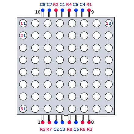
8x8 LED matrix: the details and the resistor test are in Part 10.
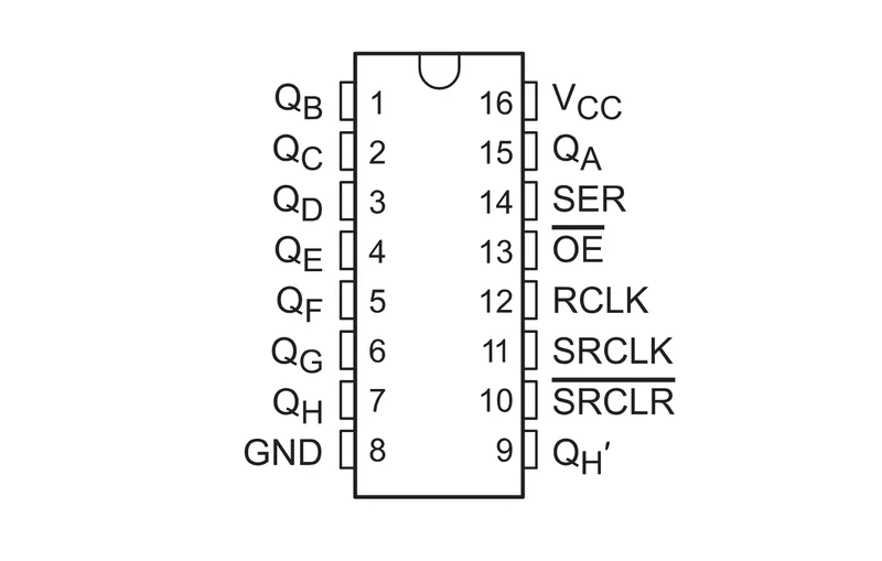
74HC595 register: the full description of the legs is in Part 13.
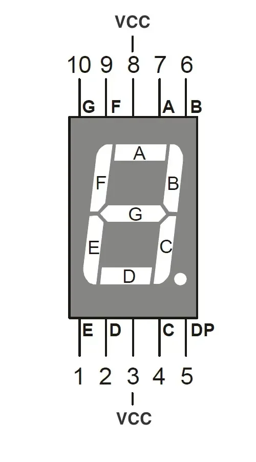
1-digit 7-segment display: the type test (cathode/anode) is in Part 9.
| Group | Board pins | Note |
|---|---|---|
| Matrix – rows R1–R8 | D9, D4, D13, D6, A3, D12, A2, D10 | unchanged, exactly as in Part 12 |
| Register – SER, SRCLK, RCLK | D2, D3, D5 | as in Part 13, but on different pins (D4 is taken by a matrix row) |
| Register – VCC, GND, OE, SRCLR | 5 V, GND, GND, 5 V | the last two “hard-wired”, as in Part 13 |
| Register QA…QH – each through 220 Ω | matrix column C1…C8 and display segment a…g / dot | 8 resistors, two jumper wires from each |
| 1-digit display – common leg | D7 | turns the score digit on/off, like a row leg of the matrix |
| Joystick – VRx, VRy | A5, A4 | unchanged |
| Joystick – SW | D8 | connected at last |
  MATRIX -> rows unchanged, see Part 12

  REGISTER:
  D2 --------- SER
  D3 --------- SRCLK
  D5 --------- RCLK
  5V --------- VCC + SRCLR
  GND -------- GND + OE

  EACH OF THE EIGHT OUTPUTS QA..QH (through 220 Ω) GOES TWO WAYS:
  QA --[ 220 Ω ]--+-- matrix column C1
                  +-- display segment a
  QB --[ 220 Ω ]--+-- matrix column C2     +-- segment b
  ...                (the same for QC..QG -> C3..C7 / c..g)
  QH --[ 220 Ω ]--+-- matrix column C8
                  +-- display dot

  1-DIGIT DISPLAY - common leg:
  D7 ---------------------------------- turns the score digit on/off

  JOYSTICK:
  VRx --- A5     VRy --- A4     SW --- D8
This is the whole circuit built on the breadboards:
Step-by-step assembly
Build the circuit on the breadboard
Loading the 3D view...
Plug in the matrix and connect the rows
Press the matrix in straddling the groove, as in Part 12, and connect its eight rows straight to pins ~9, 4, 13, ~6, A3, 12, A2, ~10. This time do not plug in the old resistors for the columns.
Order of assembly:
- 1Build the matrix and the joystick exactly as in Part 12: rows on D9, D4, D13, D6, A3, D12, A2, D10; joystick VRx→A5, VRy→A4. Do not plug in the old eight resistors for the columns: this time the register drives the columns.
- 2Press in the 74HC595 as in Part 13: VCC and SRCLR to “+”, GND and OE to “–”.
- 3SER → D2, SRCLK → D3, RCLK → D5.
- 4Eight 220 Ω resistors on outputs QA–QH. From each one run two jumper wires: one to its column of the matrix, the other to its segment of the 1-digit display (use your sheet of paper from the tests in Parts 9 and 10 so you don't mix up the legs).
- 5Common leg of the 1-digit display → D7.
- 6The joystick's
SWbutton → D8. - 7Check everything once more. Only now plug in the USB cable.
Before you flash the whole game, a quick test of the connections. This circuit has more wires than any other in the series, and hunting for a loose jumper wire in the finished Snake with a score is much harder than in a simple test. First flash this short sketch. It lights the whole matrix at once, row by row, through the register:
// Test: lights the whole matrix - checks the connections before the real program
const int rowPins[8] = {9, 4, 13, 6, A3, 12, A2, 10};
const int dataPin = 2, clockPin = 3, latchPin = 5;   // SER, SRCLK, RCLK

const int ROW_ON  = HIGH;
const int ROW_OFF = LOW;

void sendByte(byte pattern) {
  digitalWrite(latchPin, LOW);
  shiftOut(dataPin, clockPin, MSBFIRST, pattern);
  digitalWrite(latchPin, HIGH);
}

void setup() {
  for (int i = 0; i < 8; i++) pinMode(rowPins[i], OUTPUT);
  pinMode(dataPin, OUTPUT);
  pinMode(clockPin, OUTPUT);
  pinMode(latchPin, OUTPUT);
}

void loop() {
  for (int r = 0; r < 8; r++) {
    for (int i = 0; i < 8; i++) digitalWrite(rowPins[i], ROW_OFF);   // turn off all the rows
    sendByte(0x00);                                                  // all columns LOW = on
    digitalWrite(rowPins[r], ROW_ON);                                // light this one row
    delay(2);
  }
}
The matrix columns are active LOW, so shiftOut(..., 0x00) (all zeros) sets all eight outputs of the register to LOW at once, which means all the columns are on. In this test you don't have to invert anything (~) as in the real program: 0x00 inverted would give exactly the same thing.
All 64 LEDs should shine equally brightly. If something is missing, wiggle each jumper wire at the matrix, the register and the resistors in turn. A loose contact is the most common cause of dark patches, and in this circuit it can also cause symptoms somewhere else that seem to have nothing to do with it (for example a dark score display even though the code is right). Only when the whole matrix shines evenly, flash the real game from the program below.
06
Program: the whole game with a score
The game engine is Part 12, unchanged. What's new is how we draw the picture, and what we do after you lose.
// === Part 14: Snake with a scoreboard (matrix + register + 1-digit display) ===

#include <EEPROM.h>

// --- The matrix: rows unchanged from Part 12 ---
const int rowPins[8] = {9, 4, 13, 6, A3, 12, A2, 10};   // rows R1..R8

const int ROW_ON  = HIGH;    // a different type of matrix? swap HIGH and LOW in these two
const int ROW_OFF = LOW;

// --- The 74HC595 register: now it drives the matrix columns AND the score segments ---
const int dataPin  = 2;      // SER
const int clockPin = 3;      // SRCLK
const int latchPin = 5;      // RCLK

// --- The 1-digit score display ---
const int scorePin = 7;      // common leg - like a row of the matrix

const int SCORE_ON  = LOW;   // common cathode. A different type? swap HIGH and LOW in these two
const int SCORE_OFF = HIGH;

// --- The joystick ---
const int xPin       = A5;
const int yPin       = A4;
const int buttonPin  = 8;    // SW - in Part 12 there was no free pin for it

// Patterns of the digits 0-9, as in Part 13.
const byte PATTERN[10] = {
  0b00111111,  // 0
  0b00000110,  // 1
  0b01011011,  // 2
  0b01001111,  // 3
  0b01100110,  // 4
  0b01101101,  // 5
  0b01111101,  // 6
  0b00000111,  // 7
  0b01111111,  // 8
  0b01101111,  // 9
};

// --- State of the game (as in Part 12) ---
int image[8][8];

int snakeX[64];
int snakeY[64];
int length;

int  dirX, dirY;
bool directionChanged;

int  fruitX, fruitY;
bool gameOver;

unsigned long tempo;
unsigned long lastStep;

// --- Score and high score ---
const int highScoreAddress = 0;   // the EEPROM cell where we keep the high score
int highScore = 0;

void setup() {
  for (int i = 0; i < 8; i++) {
    pinMode(rowPins[i], OUTPUT);
  }
  pinMode(dataPin, OUTPUT);
  pinMode(clockPin, OUTPUT);
  pinMode(latchPin, OUTPUT);
  pinMode(scorePin, OUTPUT);
  pinMode(buttonPin, INPUT_PULLUP);

  highScore = EEPROM.read(highScoreAddress);
  if (highScore > 61) {
    highScore = 0;   // a fresh chip returns 255 from an unused cell - that is not a real score
  }

  newGame();
}

void loop() {
  if (!gameOver) {
    readJoystick();

    if (millis() - lastStep >= tempo) {
      lastStep = millis();
      moveSnake();
    }
  }

  if (gameOver) {
    int score = length - 3;
    if (score > highScore) {
      highScore = score;
      EEPROM.update(highScoreAddress, highScore);   // .update() writes only if the value has changed
    }

    for (int b = 0; b < 3; b++) {
      drawFrame();
      for (int k = 0; k < 9; k++) showFrame();
      clearImage();
      for (int k = 0; k < 9; k++) showFrame();
    }
    newGame();
  }

  drawFrame();
  showFrame();
}

// -- Set up a new game (as in Part 12) --
void newGame() {
  length = 3;
  snakeX[0] = 4; snakeY[0] = 4;
  snakeX[1] = 3; snakeY[1] = 4;
  snakeX[2] = 2; snakeY[2] = 4;
  dirX = 1; dirY = 0;
  directionChanged = false;
  tempo = 400;
  lastStep = millis();
  gameOver = false;
  randomSeed(millis());
  newFruit();
}

// -- Read the joystick (as in Part 12) --
void readJoystick() {
  if (directionChanged) return;

  int x = analogRead(xPin);
  int y = analogRead(yPin);

  if      (x > 800 && dirX == 0) { dirX =  1; dirY =  0; directionChanged = true; }
  else if (x < 200 && dirX == 0) { dirX = -1; dirY =  0; directionChanged = true; }
  else if (y > 800 && dirY == 0) { dirX =  0; dirY =  1; directionChanged = true; }
  else if (y < 200 && dirY == 0) { dirX =  0; dirY = -1; directionChanged = true; }
}

// -- One step of the snake (as in Part 12) --
void moveSnake() {
  directionChanged = false;

  int newX = snakeX[0] + dirX;
  int newY = snakeY[0] + dirY;

  if (newX < 0 || newX > 7 || newY < 0 || newY > 7) { gameOver = true; return; }
  if (onSnake(newX, newY)) { gameOver = true; return; }

  bool ate = (newX == fruitX && newY == fruitY);
  if (ate && length < 64) length = length + 1;

  for (int i = length - 1; i > 0; i--) {
    snakeX[i] = snakeX[i - 1];
    snakeY[i] = snakeY[i - 1];
  }
  snakeX[0] = newX;
  snakeY[0] = newY;

  if (ate) {
    newFruit();
    if (tempo > 150) tempo = tempo - 30;
  }
}

// -- Is the square (x, y) taken by the snake? (as in Part 12) --
bool onSnake(int x, int y) {
  for (int i = 0; i < length; i++) {
    if (snakeX[i] == x && snakeY[i] == y) return true;
  }
  return false;
}

// -- New food on a random free square (as in Part 12) --
void newFruit() {
  if (length >= 64) { gameOver = true; return; }
  do {
    fruitX = random(8);
    fruitY = random(8);
  } while (onSnake(fruitX, fruitY));
}

// -- Build the 'image' array from the snake and the fruit (as in Part 12) --
void drawFrame() {
  clearImage();
  for (int i = 0; i < length; i++) {
    image[ snakeY[i] ][ snakeX[i] ] = 1;
  }
  if ((millis() / 200) % 2 == 0) {
    image[fruitY][fruitX] = 1;
  }
}

// -- Turn off the whole image (as in Part 12) --
void clearImage() {
  for (int r = 0; r < 8; r++) {
    for (int c = 0; c < 8; c++) {
      image[r][c] = 0;
    }
  }
}

// -- Send one byte to the register (as in Part 13) --
void sendByte(byte pattern) {
  digitalWrite(latchPin, LOW);
  shiftOut(dataPin, clockPin, MSBFIRST, pattern);
  digitalWrite(latchPin, HIGH);
}

// -- Turn one row of the image (eight 0/1) into one byte for the register --
byte rowToByte(int r) {
  byte b = 0;
  for (int c = 0; c < 8; c++) {
    bitWrite(b, c, image[r][c]);   // bit c = the value of column c in this row
  }
  return b;
}

// -- One full frame: eight rows of the matrix + one score digit --
void showFrame() {
  digitalWrite(scorePin, SCORE_OFF);   // the score digit stays off for the whole matrix

  for (int r = 0; r < 8; r++) {
    for (int i = 0; i < 8; i++) digitalWrite(rowPins[i], ROW_OFF);

    byte rowByte = rowToByte(r);
    sendByte(~rowByte);                // the matrix columns are active LOW - we invert

    digitalWrite(rowPins[r], ROW_ON);
    delay(2);
  }

  for (int i = 0; i < 8; i++) digitalWrite(rowPins[i], ROW_OFF);   // now the matrix is off

  int score = length - 3;
  int shown = score;
  if (digitalRead(buttonPin) == LOW) {   // you hold the button - show the high score instead
    shown = highScore;
  }

  byte digitByte = PATTERN[shown % 10];   // the last digit
  if (shown >= 10) {
    bitSet(digitByte, 7);                 // the dot = "10 or more"
  }
  sendByte(digitByte);                    // the segments are active HIGH - no inverting

  digitalWrite(scorePin, SCORE_ON);
  delay(2);
}
Write this program in your browser
Tutorial on the left, editor on the right. Build your code and flash it to the board in one click, with nothing to install.
| Instruction | What it does |
|---|---|
#include <EEPROM.h> + EEPROM.read / .update | reading and saving the high score in permanent memory (Where you know it from: new – EEPROM (mentioned in Part 4)) |
if (highScore > 61) highScore = 0; | a fresh chip returns 255 – that is not a real score (Where you know it from: new) |
rowToByte(r) + bitWrite(b, c, ...) | turns one row of image[8][8] into a byte for the register (Where you know it from: new – bitWrite) |
sendByte(~rowByte) to matrix | the byte inverted – the columns are active LOW (Where you know it from: Parts 10 and 13, taken further) |
sendByte(digitByte) to display | the byte as it is – the segments are active HIGH (Where you know it from: Part 13) |
score % 10 + bitSet(digitByte, 7) | the last digit of the score, plus the dot as “10 or more” (Where you know it from: Part 9 (division, %) + new (bitSet)) |
digitalRead(buttonPin) == LOW in showFrame() | holding the button shows the high score instead of the score (Where you know it from: Part 5 (INPUT_PULLUP)) |
other functions (newGame, readJoystick, moveSnake, onSnake, newFruit, drawFrame, clearImage) | the game engine (Where you know it from: unchanged – Part 12) |
Flash the code through FlashESP.com. The snake works as in Part 12, and next to it you see a digit. It grows with each fruit you eat, and after the tenth the dot lights up. Lose a few times on purpose and check two things: after you beat the high score, holding the joystick button shows the new, higher value, and after you unplug the USB and plug it back in, the high score is still there.
Build checklist
Tick them off one by one. Your progress is saved in this browser.
0 / 17
Rules worth remembering
- 1
The matrix and the score never shine in the same microsecond.
That is why they can share the same eight outputs of the register: multiplexing switches between them, just as it switches between the rows in Part 10.
- 2
The same byte means something different to each receiver.
The matrix columns are active LOW (you invert the byte:
~rowByte), the display segments are active HIGH (the byte as it is). Mixing the two up gives either gibberish or a negative. - 3
EEPROM.update(), notEEPROM.write().The first one writes only when the value really changes. That saves the limited life of the memory when you test often.
- 4
The high score survives the power going off; the game does not.
That is on purpose: the game itself always starts again after you lose, but the best score is saved for good.
Projects
None of the projects below needs anything extra: they all build on the same game. They go from the easiest to the most ambitious.
- 1
Reset the high score
Easy- What you will use
- this game
- What you will learn
- making a joystick button held down at startup (in
setup()) write0to the EEPROM – a fresh start
- 2
A different threshold for the dot
Easy- What you will use
- this game
- What you will learn
- setting, for example, “5 or more” instead of “10 or more” – changing one number in the condition
- 3
The dot blinks at a new high score
Medium- What you will use
- this game
- What you will learn
- adding an extra variable “I've just beaten the high score” and blinking the dot for the first few seconds after you lose
- 4
Two digits one after the other
Medium- What you will use
- this game
- What you will learn
- showing the tens and the ones in turn, every half second, instead of the dot – the full number on one digit
- 5
A ranking of the top three scores
Challenging- What you will use
- this game
- What you will learn
- using three EEPROM cells instead of one and putting a new score in the right place in the list
Summary
Nothing in this part is a new piece of hardware. It is Part 12 and Part 13 put together into one whole, plus one trick: the same register can drive two devices, as long as they never shine at the same time. An inverted byte for the matrix, the byte as it is for the display, and twelve pins are enough for the game, the score and the button that had nowhere to connect in Part 12.
This closes the game section. You started with a single lit LED in Part 4 and ended up with a snake with a score and a high score kept in permanent memory. The next section changes the subject: sensors, which let the Arduino see, hear and feel the world around it.