XXL Kit for Arduino · Shift register
Part 13 The shift register: three pins instead of eight
- Beginner
- Ages 8+
- about 60 min
In Part 12, Snake took up all the pins of the R3 board. To add anything at all to the game, even a score counter, you first have to win some pins back. That is the job of the 74HC595 shift register: a chip that turns 3 Arduino pins into 8 outputs, and, when you link several of them in a chain, into as many as you like. In this part you get to know it on a separate demo: the 4-digit display from Part 9, which will now take seven pins instead of eleven.
Who is it for? For children and teenagers aged 8 and up, for teachers, and for adults who have done Parts 9 and 12: it helps to know the table of digit patterns and the multiplexing from Part 9. Here we connect them differently, but the idea stays the same.
01
Out of pins
Every bigger project hits this wall sooner or later. Snake hit it in Part 12.
The R3 board gives you about 18 input/output pins: the digital pins D2–D13 (D0 and D1 are taken by the connection to the computer) and the analog pins A0–A5, which work just as well as digital ones. That is a lot, as long as you connect one or two parts. But in Part 12 it came out like this:
- the 8x8 matrix from Part 10 takes 16 pins (8 rows + 8 columns),
- the joystick from Part 11 takes 2 pins (the X and Y axes),
- together that makes 18 out of 18. Not a single free pin was left for the stick's button, let alone for a score display.
You could buy a bigger board. Or you can do what real devices with hundreds of LEDs do: add a shift register. One small chip from the kit (item 32 from Part 1) turns 3 Arduino pins into 8 outputs.
02
The 74HC595 shift register
Imagine a narrow pipe that you drop eight marbles into, one after another. When they are all inside, you open a flap, and all eight fall out at once, each through its own hole.
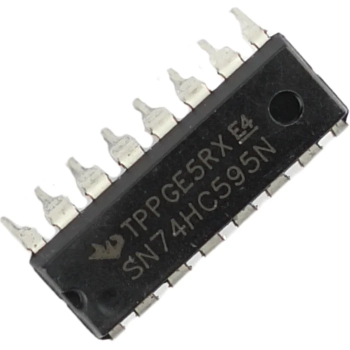
From the kit
74HC595N shift register
Eight outputs on three pins. You send it a number bit by bit over one wire. The second wire is the clock, which says “now the next bit”. The chip remembers the last eight bits and puts them out on eight of its legs. The third wire, the latch, decides when the outputs change.
Put more simply, it is a serial-to-parallel converter. “Serial” means “one after another, over one wire”: that is how the data comes in. “Parallel” means “all at once, each over its own wire”: that is how it goes out. The register turns one into the other.
There are three control wires. In this guide we call them by the names printed on the picture of the chip in the next section:
| Role | Leg | What it is for |
|---|---|---|
data – SER | 14 | the bits come in here, one after another |
clock – SRCLK | 11 | each pulse pushes the next bit inside |
latch – RCLK | 12 | a pulse copies the eight bits that were pushed in onto the outputs, all at once |
The latch is there so that the outputs do not “flicker” with in-between patterns while the bits are sliding in. You quietly push in all eight, then give the latch one pulse, and all eight outputs change at the same moment.
03
The legs of the chip
Sixteen legs, but only five of them need any thinking. The rest go straight to plus or minus for good.
The 74HC595 sits in a case with 16 legs, 8 on each side. There is no writing on the chip itself, only a notch at one end and the rows of legs. Leg number 1 is next to the notch, and you count from there; for the rest, hold the chip next to the picture.
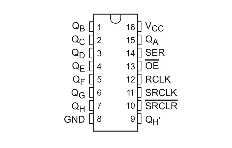
We stick to the names from this picture. In other sources (other manufacturers' datasheets, other people's modules) the same legs are sometimes labeled differently (the “also called” column):
| Leg | Name (as in the picture) | Also called | What it is for |
|---|---|---|---|
| 16 | VCC | – | power → 5 V |
| 8 | GND | – | ground → GND |
| 15, 1–7 | QA–QH | Q0–Q7 | eight outputs: what you sent shows up here |
| 14 | SER | DS, SI | data: the bits come in here |
| 11 | SRCLK | SHCP, SCK | clock: each pulse pushes the next bit in |
| 12 | RCLK | STCP, RCK | latch: shows the eight bits at once |
| 13 | OE | – | switches the outputs on → permanently to GND |
| 10 | SRCLR | MR | reset → permanently to 5 V |
| 9 | QH' | Q7S | the “exit” for bits going on to the next register (last section) |
Only SER, SRCLK and RCLK (legs 14, 11, 12) go to the Arduino pins. VCC and GND go to the power rails. OE and SRCLR must not be left free: without the OE→GND jumper wire the outputs are dead, and without SRCLR→5 V the register keeps resetting itself over and over. This is the most common mistake: the chip has power, shiftOut runs, and nothing shows up on the outputs.
04
Building the demo: the 4-digit display through the register
The same display as in Part 9 and the same table of digit patterns. Only now the eight segment lines go through the register.
What you need: the breadboard, the R3 board, the 74HC595 register, the 4-digit 7-segment display, eight 220 Ω resistors, about 15 male-to-male jumper wires.
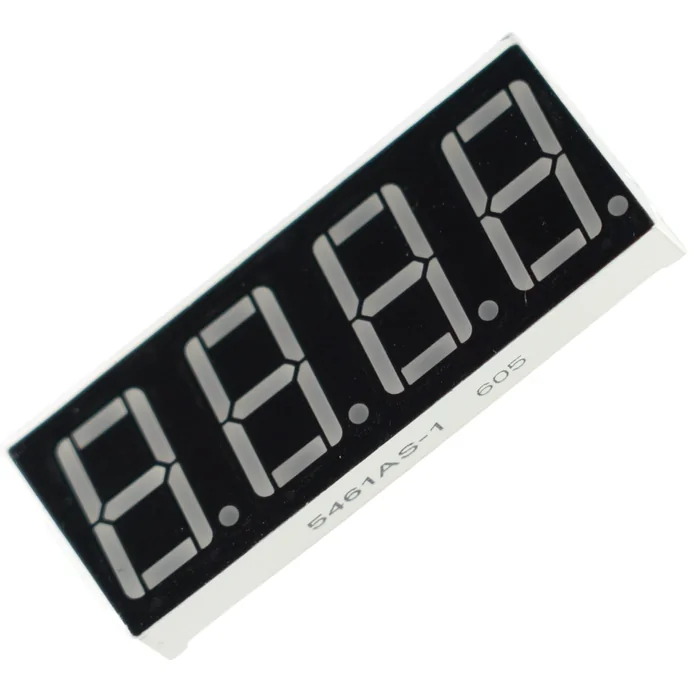
From the kit
4-digit 7-segment display
You know it from Part 9: four digits sharing eight segment lines, a–g plus the dot. You check its type (common cathode or anode) the same way: the resistor test is in Part 9.
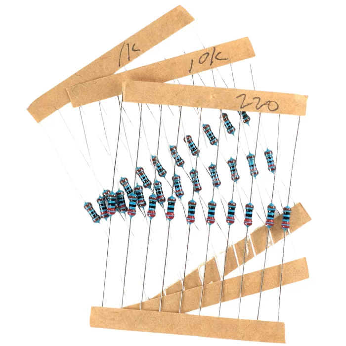
From the kit
Eight 220 Ω resistors
One for each output of the register, QA–QH. The resistor protects a segment just as it protects an ordinary LED. The only difference is that its other end sits on a leg of the register, not of the board.
| Pin | Goes to | Note |
|---|---|---|
| 595: VCC (16), GND (8) | 5 V, GND | power for the chip |
| 595: OE (13) | GND | permanently – switches the outputs on |
| 595: SRCLR (10) | 5 V | permanently – switches the reset off |
| 595: SER (14) | D2 | data |
| 595: SRCLK (11) | D3 | clock |
| 595: RCLK (12) | D4 | latch |
| 595: QA…QH | segments a, b, c, d, e, f, g, dot | each through a 220 Ω resistor |
| 595: QH' (9) | – | not connected in this demo |
| display: digit select 1–4 | D5, D6, D7, D8 | straight to the board |
With a single register, QH' (leg 9) stays free. That is not a mistake, and you do not have to connect anything to it. It is an output, so even “floating” it does not pick up interference the way an input without a pull-up resistor does (Part 5). It only becomes useful when you add a second register: see the last section of this part.
  ARDUINO            74HC595                     4-DIGIT DISPLAY
  D2 --------- SER(14)
  D3 --------- SRCLK(11)
  D4 --------- RCLK(12)
  5V --------- VCC(16) + SRCLR(10)
  GND -------- GND(8)  + OE(13)

                QA(15) --[ 220 Ω ]-- segment a
                QB(1)  --[ 220 Ω ]-- segment b
                QC(2)  --[ 220 Ω ]-- segment c
                QD(3)  --[ 220 Ω ]-- segment d
                QE(4)  --[ 220 Ω ]-- segment e
                QF(5)  --[ 220 Ω ]-- segment f
                QG(6)  --[ 220 Ω ]-- segment g
                QH(7)  --[ 220 Ω ]-- dot

  D5 ---------------------------------- digit select 1
  D6 ---------------------------------- digit select 2
  D7 ---------------------------------- digit select 3
  D8 ---------------------------------- digit select 4
This is the whole demo built on the breadboard:
Step-by-step assembly
Build the circuit on the breadboard
Loading the 3D view...
Plug in the register and the display
Press the 74HC595 in straddling the groove, with the notch to the right: leg 1 is then in the top right corner. Next to it, on the left, press in the 4-digit 7-segment display, also straddling the groove.
Order of assembly:
- 1Press the 74HC595 into the breadboard straddling the groove, with the notch towards one end. Remember where leg 1 is.
- 2The permanent jumper wires: legs 16 and 10 to the “+” rail (5 V), legs 8 and 13 to the “–” rail (GND).
- 3SER (14) → D2, SRCLK (11) → D3, RCLK (12) → D4.
- 4Eight 220 Ω resistors: each one with one end in a leg QA–QH and the other end to the matching segment of the display (
a–gand the dot). - 5The four digit-select legs of the display → D5, D6, D7, D8.
- 6Check everything once more. Only now plug in the USB cable.
05
The program: a counter 0000–9999
shiftOut sends a byte to the register. The rest, multiplexing the four digits, is exactly Part 9 again.
We now keep the pattern of each digit as a byte: eight bits, one for each output of the register. 1 means “the segment shines”, 0 means “dark”.
  0b01001111   <- pattern of the digit "3"
    ||||||||
    |||||||+-- segment a  (1 = lit)
    ||||||+--- segment b
    |||||+---- segment c
    ||||+----- segment d
    |||+------ segment e
    ||+------- segment f
    |+-------- segment g
+--------- dot// === Part 13: a counter 0000-9999 on the 4-digit display through the 74HC595 register ===
const int dataPin = 2; // SER - serial data to the register
const int clockPin = 3; // SRCLK - a pulse pushes the next bit in
const int latchPin = 4; // RCLK - a pulse shows 8 bits at once
const int digitPins[4] = {5, 6, 7, 8}; // digit select 1-4 (straight to the board)
// The type of display as in Part 9. Common cathode by default.
const int DIGIT_ON = LOW; // this digit is on
const int DIGIT_OFF = HIGH;
// Patterns of the digits 0-9. Bits from the right: a, b, c, d, e, f, g, dot.
const byte PATTERN[10] = {
0b00111111, // 0
0b00000110, // 1
0b01011011, // 2
0b01001111, // 3
0b01100110, // 4
0b01101101, // 5
0b01111101, // 6
0b00000111, // 7
0b01111111, // 8
0b01101111, // 9
};
int number = 0;
unsigned long lastSecond = 0;
void setup() {
pinMode(dataPin, OUTPUT);
pinMode(clockPin, OUTPUT);
pinMode(latchPin, OUTPUT);
for (int i = 0; i < 4; i++) pinMode(digitPins[i], OUTPUT);
}
void loop() {
// +1 every second (millis, as in Part 9 - the loop does not stop)
if (millis() - lastSecond >= 1000) {
lastSecond = millis();
number = number + 1;
if (number > 9999) number = 0;
}
showNumber(number); // keep refreshing the four digits
}
// Send one byte to the register and show it on the outputs QA-QH.
void sendByte(byte pattern) {
digitalWrite(latchPin, LOW); // close the latch - the outputs are frozen
shiftOut(dataPin, clockPin, MSBFIRST, pattern); // shift out 8 bits, bit by bit
digitalWrite(latchPin, HIGH); // revealed: all eight bits at once
}
// Show a 4-digit number (multiplexing as in Part 9).
void showNumber(int n) {
int digits[4] = { (n / 1000) % 10, (n / 100) % 10, (n / 10) % 10, n % 10 };
for (int d = 0; d < 4; d++) {
for (int i = 0; i < 4; i++) digitalWrite(digitPins[i], DIGIT_OFF); // turn them all off
sendByte(PATTERN[ digits[d] ]); // the pattern of this digit
digitalWrite(digitPins[d], DIGIT_ON); // light this one
delay(3);
}
}
Write this program in your browser
Tutorial on the left, editor on the right. Build your code and flash it to the board in one click, with nothing to install.
| Instruction | What it does |
|---|---|
shiftOut(dataPin, clockPin, MSBFIRST, pattern) | sends a byte to the register bit by bit (Where you know it from: new in this part) |
digitalWrite(latchPin, LOW / HIGH) around shiftOut | the outputs change only once they are “revealed” (Where you know it from: new in this part – the latch) |
const byte PATTERN[10] with 0b… | the pattern of a digit as 8 bits = the 8 outputs of the register (Where you know it from: new in this part – byte and binary notation) |
for (int d = 0; d < 4; d++) + digitPins | multiplexing the four digits (Where you know it from: Part 9 (unchanged)) |
(n / 100) % 10 etc. | splitting the number into single digits (Where you know it from: Part 9) |
millis() - lastSecond >= 1000 | +1 every second, without a delay in the loop (Where you know it from: Part 9) |
Flash the code through FlashESP.com. The display counts 0000, 0001, 0002… one step every second, all the way to 9999. This takes 7 pins (D2–D8) instead of the eleven from Part 9. If the digits shine “in negative” or not at all, it is the type of display (common anode): look at the test in Part 9, and in the code send ~PATTERN[...] (the ~ sign flips all the bits) and swap DIGIT_ON with DIGIT_OFF. If the display stays completely dark even though the code is right, check the OE→GND and SRCLR→5 V jumper wires.
06
A chain of registers
One register gives you 8 outputs. But the QH' leg passes the “extra” bits on to the next one, and so on forever, still on three pins.
When you push a ninth bit into the register, the first one “falls out” through the QH' leg. Connect QH' of one chip to SER of a second one (the clock and the latch shared by both), and the two registers behave like one with 16 outputs. Three, four, ten: the idea is the same, and there are still only three Arduino pins.
Not much changes in the code: between LOW and HIGH on the latch you call shiftOut as many times as you have registers. First the byte for the farthest one, last the byte for the nearest.
digitalWrite(latchPin, LOW);
shiftOut(dataPin, clockPin, MSBFIRST, byte2);  // the first register pushes it on to the second
shiftOut(dataPin, clockPin, MSBFIRST, byte1);  // this one stays in the first
digitalWrite(latchPin, HIGH);
The kit has one 74HC595, so you cannot build a chain right now. But this very trick is what drives boards with thousands of LEDs. In Part 14 we will use a single register more cleverly: the same eight outputs will take turns serving the Snake matrix and a digit showing the score.
Build checklist
Tick them off one by one. Your progress is saved in this browser.
0 / 15
Rules worth remembering
- 1
OE to ground, SRCLR to plus, permanently.
Without these two jumper wires the register has power and
shiftOutruns, but the outputs are dead. It is the first thing to check when “nothing lights up”. - 2
The latch (RCLK) wraps
shiftOut.LOWbefore,HIGHafter. Otherwise the outputs flash in-between patterns while the bits slide in. - 3
A register does not “boost” the current.
Every output
QA–QHstill needs a resistor next to its segment or LED, just like an Arduino pin. The 74HC595 gives you more outputs, not more power. - 4
A bit in the byte = an output of the register.
You read
PATTERNfrom the right: bit 0 isQA, bit 7 isQH. Bits in the wrong order mean the wrong segments.
Projects
None of the projects below needs anything extra: they all build on the same demo. They go from the easiest to the most ambitious.
- 1
Words instead of digits
Easy- What you will use
- this demo
- What you will learn
- adding to
PATTERNthe letters you can make from seven segments (A,E,H,L,P,d,o) and showing a short word
- 2
Counting up and down
Easy- What you will use
- this demo + 1 button (Part 5)
- What you will learn
- switching the counting direction with one button – there is still a free pin for it
- 3
Eight LEDs instead of the display
Medium- What you will use
- the register + 8 LEDs + 8 resistors
- What you will learn
- using the same register with LEDs on its outputs: a “bar” or a binary counter – one byte controls eight LEDs
- 4
Electronic dice on the register
Medium- What you will use
- the register + 7 LEDs + 7 resistors
- What you will learn
- arranging seven LEDs like the dots on a die, with
randompicking a pattern 1–6 as a byte
- 5
A minutes:seconds clock
Challenging- What you will use
- this demo
- What you will learn
- counting seconds and showing
MM:SS, with the dot between the digits as the colon – it combinesmillis(),/ 60,% 60and multiplexing
Summary
A shift register solves one particular problem: too few pins. You send it a byte over three wires (shiftOut plus a pulse on the latch), and it puts those eight bits out on eight outputs. The digit pattern that in Part 9 took seven separate digitalWrite calls is now a single number in binary: bit by bit, output by output.
This was the last building block before the finale of the section. In Part 14 we go back to Snake: one register will take turns serving the game screen and a digit showing the score, and we will save the high score so that it survives switching off the power.